Objective
The main purpose of modeling was to characterize the topography of the kinetics behind foreign protein/product production in recombinant E.Coli biofilm with a diffusing inducer, and the effect on the various species involved by primarily the following factors:
- Time-derivative Spatial-Gradient Inducer Concentration
- Repressor Concentration
- Ribosome Binding Site (Rate of Transcription)
In terms of our iGEM project, this model was employed to explore the effect of IPTG concentration and diffusion, lacI concentration (determined by the combination part of constitutive promoter, ribosome binding site, lacI gene, double terminator, lac promoter/operon), and the ribosome binding site on the concentrations of all species involved - described in the following sections - and especially on Chitin Synthase and Chitin concentration and the corresponding rates.
Modeling
Overall Model
Using enzyme kinetics equations, we elected to mathematically simulate the following model:
Variables
- Iex: External Inducer, determined by diffusion through Fick's law (IPTG in our experiment)
- Iin: Internal Inducer (IPTG)
- Ii: Inducer bound to Repressor (IPTG bound to lacI)
- i: Repressor (lacI)
- Db: Repressor-bound DNA (lacI-bound DNA(CHS3) region in plasmid)
- Dunb: transcribe-able or Repressor-unbound DNA (lacI-unbound DNA(CHS3))
- Re: mRNA for Enzyme (CHS3 mRNA)
- E: Enzyme (CHS3)
- S: Substrate (N-Acetyl Glucosamine)
- C: Enzyme Substrate Complex (CHS3-(N-Acetyl-Glucosamine)-Chitin or (NAG)n Complex)
- P: Protein Product (Chitin or (NAG)n+1)
Equations
The differential of the variables were found as follows:
- dIin = kIin*Iex - kIex*Iin + kIir*Ii - kIif*Iin*i
- dIi = kIif*Iin*i - kIir*Ii
- di = kIir*Ii - kIif*Iin*i + kDbr*Db - kDbf*i*Dunb
- dDb = kDbf*i*Dunb - kDbr*Db
- dDunb = kDbr*Db - kDbf*i*Dunb
- dRe = ktscribe*Dunb - kRdeg*Re
- dE = ktslate*Re - kEdeg*E + kCr*CC + kP*CC - kCf*E*Si
- dSi = ksin*So - kCf*E*Si + kCr*CC
- dCC = kCf*E*Si - kCr*CC - kP*CC
- dP = kP*CC - kPdeg*P
IPTG Diffusion
First, Fick's Law of Diffusion was modeled through MATLAB. The diffusion constant used was 220um^2/s.[4]
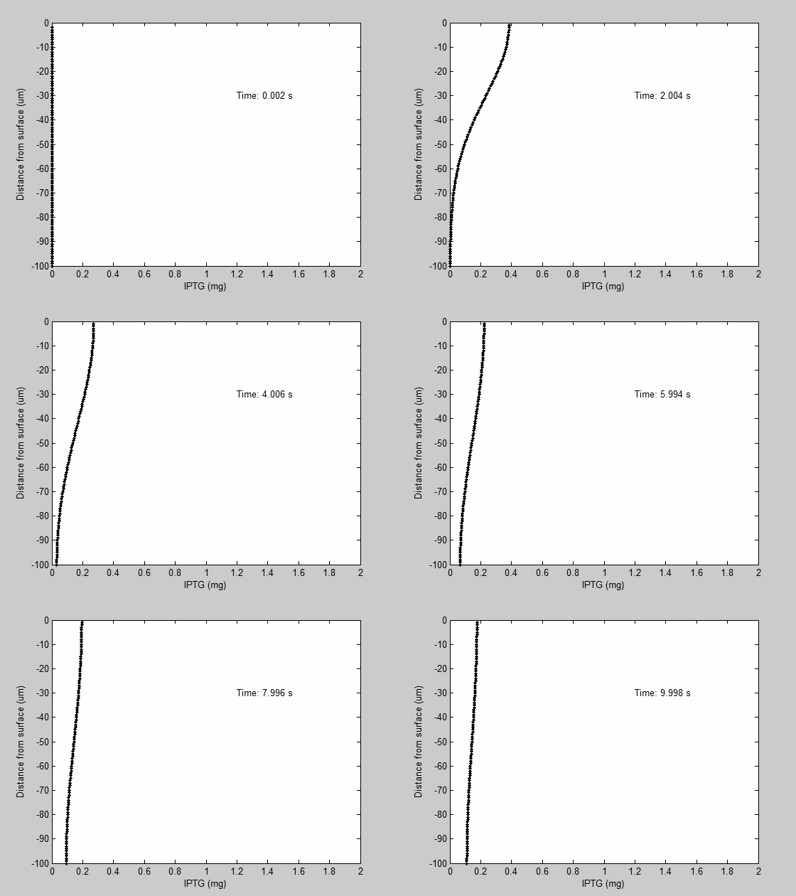
IPTG was sprayed at the top of the colony, which then diffuses as according to Fick's law.
The spatially different local IPTG concentration will then differentially induce downstream processes.
This distinction was necessary in our project in order to establish a Chitin layer on the top of the biofilm.
Semi-Empirical Variable/Constant Determination
Status: Under Development
The initial plan was to use lacI-constitutive expression / lac-operon (CP-LacpI) part with Green Fluorescent Protein to acquire empirical data.
By testing various combinations of CP/LacpI, RBS, and IPTG concentrations, the acquisition of a broad range of expression level (GFP fluorescence) over time could be acquired through a plate reader.
This data would be used to determine many of the rate constants as well as initial concentration values, thus generating a more accurate semi-empirical kinetics model.
However, at the time of the wiki-freeze, data acquisition is incomplete.
Current Model
The plots of the non-induced and the induced system are as follows:
| | Not Induced | Induced
|
| External IPTG |  | 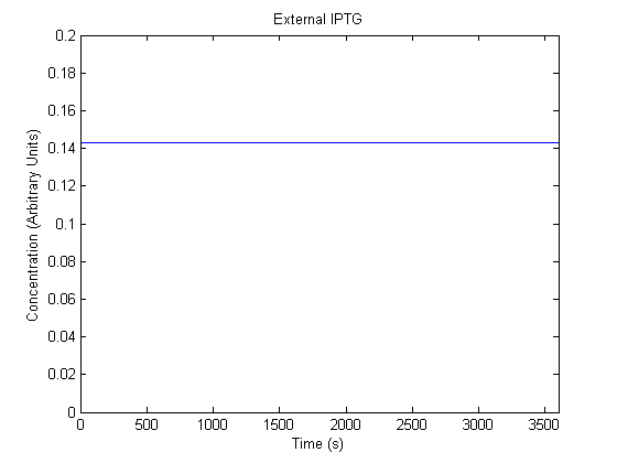
|
| Internal IPTG |  | 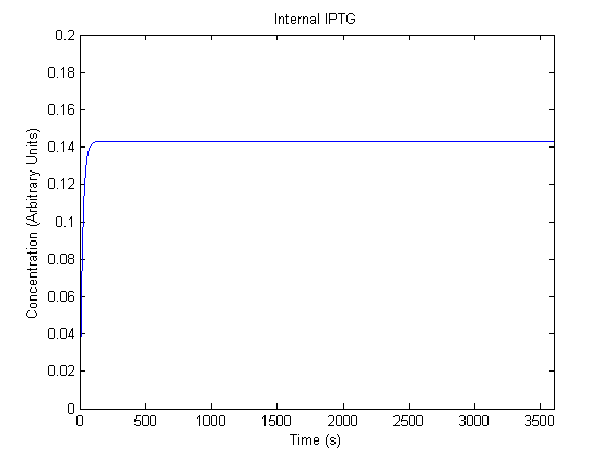
|
| IPTG bound Lac Repressor |  | 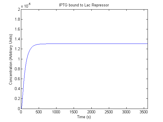
|
| Free Lac Repressor | 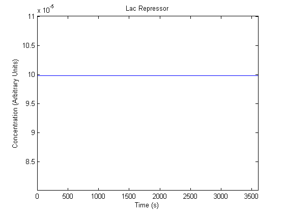 | 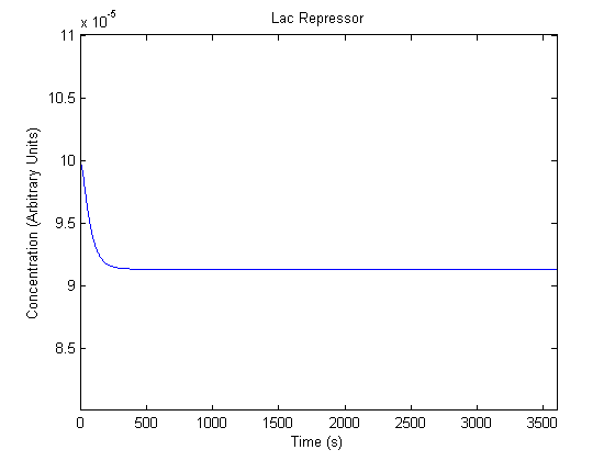
|
| Repressor Bound DNA | 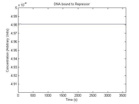 | 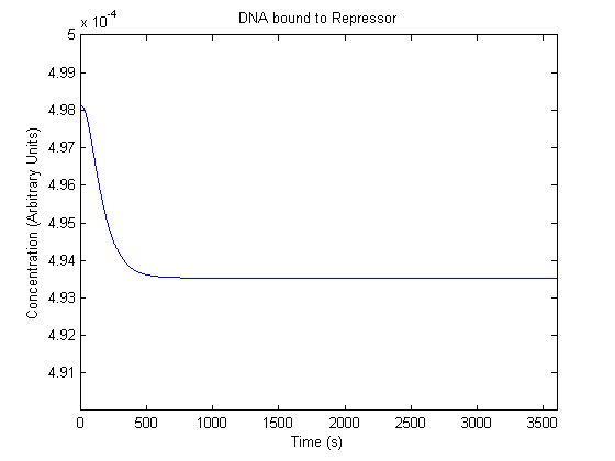
|
| Free DNA | 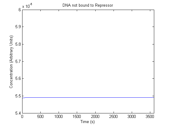 | 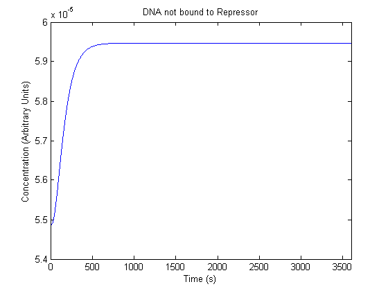
|
| mRNA | 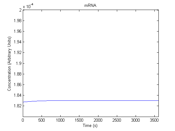 | 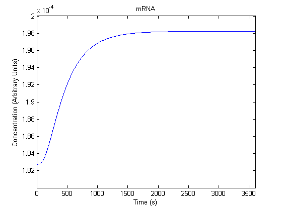
|
| Chitin Synthase 3 | 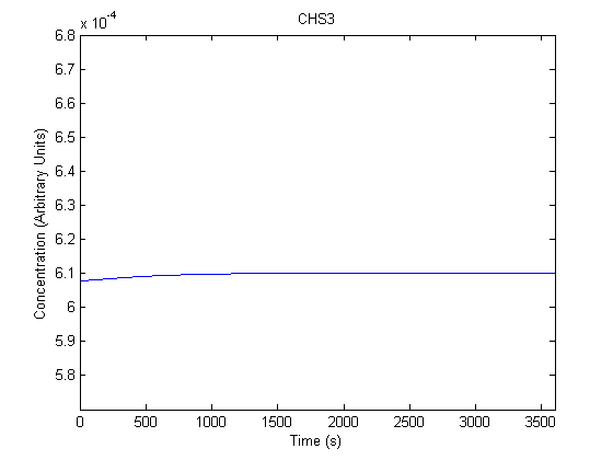 | 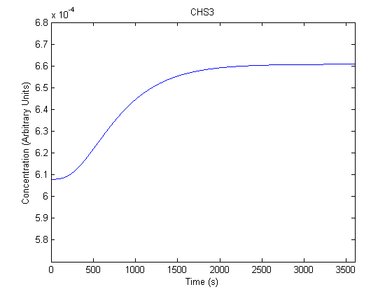
|
| N-Acetyl-Glucosamine | 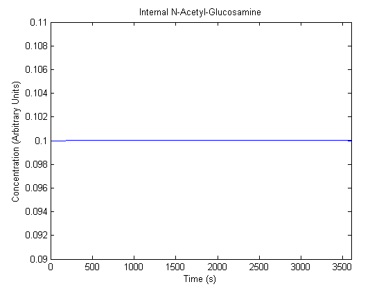 | 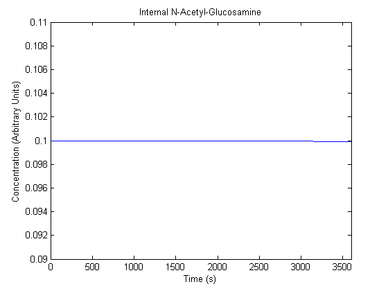
|
| CHS3-NAG/Chitin Complex | 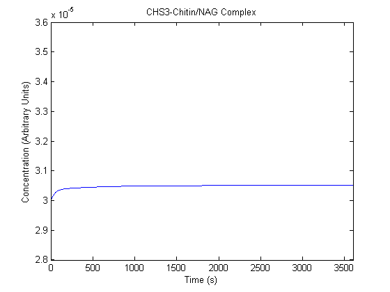 | 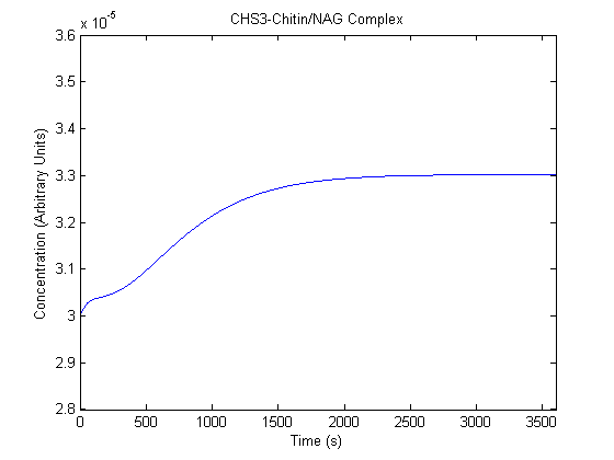
|
| Chitin |  | 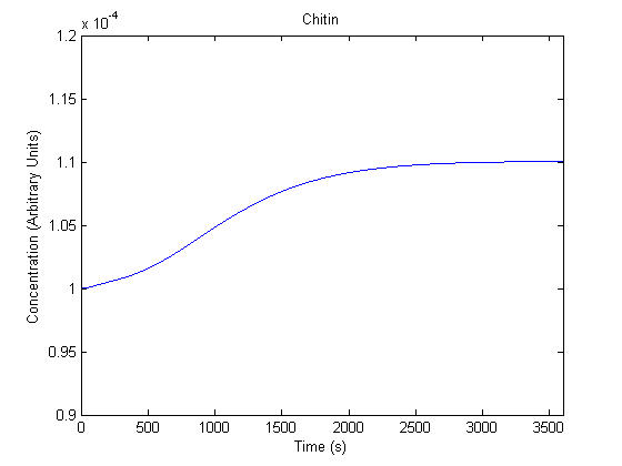
|
Future Concerns
Overall, the model, though logical, is not yet fit for application, mostly due to the lack of empirical data to which the model could be fit and/or tested. Once fit, the rate constant values and initial concentration values will be much more accurate. The following concerns deal primarily with problems that could possibly not be corrected even with empirical data.
- Currently the model predicts the final product expression level between the top layer and bottom layer of a gradient-induced system as only about 0.00001%. Determine if this is primarily due to model inaccuracy or the inefficacy of diffusion-based layer differential induction method.
- Currently the model only predicts only a 10% increase in product when induced by what is suspected to be a significant concentration of inducer. This could be due to a model design problem.
- The model assumes constant substrate; this assumption may or may not be accurate.
- The model assumes all components are in first order; this assumption may or may not be sufficient.
Future Work
Aside from being generally accurate, the model should perform the following functions:
- Differentiate protein production between the top and bottom layer of the biofilm based on a diffusion-gradient inducer.
- Differentiate protein production between expression vectors with different repressor production levels.
- Differentiate protein production between expression vectors with different IPTG Induction levels.
- Differentiate protein production between expression vectors with different Promoters (k-transcribe).
- Differentiate protein production between expression vectors with different Ribosome Binding Sites (k-translate).
- Differentiate protein production between expression vectors with different Copy Number Plasmids.
References
1. A novel structured kinetic modeling approach for the analysis of plasmid instability in recombinant bacterial cultures
William E. Bentley, Dhinakar S. Kompala
Article first published online: 18 FEB 2004
DOI: 10.1002/bit.260330108
http://onlinelibrary.wiley.com/doi/10.1002/bit.260330108/pdf
2. Mathematical modeling of induced foreign protein production by recombinant bacteria
Jongdae Lee, W. Fred Ramirez
Article first published online: 19 FEB 2004
DOI: 10.1002/bit.260390608
http://onlinelibrary.wiley.com/doi/10.1002/bit.260390608/pdf
3. Pool Levels of UDP N-Acetylglucosamine and UDP NAcetylglucosamine-Enolpyruvate in Escherichia coli and Correlation with Peptidoglycan Synthesis
DOMINIQUE MENGIN-LECREULX, BERNARD FLOURET, AND JEAN VAN HEIJENOORT*
E.R. 245 du C.N.R.S., Institut de Biochimie, Universit' Paris-Sud, Orsay, 91405, France
Received 9 February 1983/Accepted 15 March 1983
http://www.ncbi.nlm.nih.gov/pmc/articles/PMC217602/pdf/jbacter00247-0262.pdf
4. Diffusion in Biofilms
Philip S. Stewart
Center for Biofilm Engineering and Department of Chemical Engineering, Montana
State University–Bozeman, Bozeman, Montana, 59717-3980
http://www.ncbi.nlm.nih.gov/pmc/articles/PMC148055/pdf/0965.pdf
5. Regulation of the Synthesis of the Lactose Repressor
PATRICIA L. EDELMANN' AND GORDON EDLIN
Department of Genetics, University of California, Davis, California 95616
Received for publication 21 March 1974
http://www.ncbi.nlm.nih.gov/pmc/articles/PMC245824/pdf/jbacter00335-0105.pdf
MATLAB m-file
%IPTG PREDETERMINATION
%finite difference method
%diffusion equation (Fick's 2nd Law)
%c=c0*(erfc*x/sqrt(2*D*t))
%D*(Ci+1-2C+Ci-1)/dx^2 = Ci/dt
%x goes from 0 (top) to 100 micrometers
%D=IPTG is a modified monosaccharide, so we can estimate from Table 1 that
%its diffusion coefficient in water at 25°C will be ca. 6.5 × 10?6 cm2 s?1.
%Scaling to 37°C and taking De/Daq to be 0.25, De is found to be 2.2 × 10?6 cm2 s?1
%http://www.ncbi.nlm.nih.gov/pmc/articles/PMC148055/
%%
clear
clc
%INITIALIZE
D=220; %um^2/s
c0=14.298; %mg so 3ml spray of 20mM iptg
%in comparison 23.83mg of iptg is in 5ml 20mM
dx=1; %um
xmax=100; %um; 100um total
dt=.002; %s
tmax=10; %s; 1 hour total
C=zeros(xmax/dx,tmax/dt); %rows = same time %also, (x,t) x is row, t is column
C_Rate=zeros(xmax/dt,1);
C(1,1)=c0;
%Time Step
for t=1:1:tmax/dt-1; %s
   for x=1:1:(xmax/dx) %um
       if x==1%account for x=1 boundary condition
           C_Rate(x)=D*(C(x+1,t)-C(x,t))/(dx^2);
       elseif x==xmax/dx %account for x=xmax boundary condition
           C_Rate(x)=D*(C(x-1,t)-C(x,t))/(dx^2);
       else%BULK
           C_Rate(x)=D*(C(x-1,t)+C(x+1,t)-2*C(x,t))/(dx^2);
       end
       C(x,t+1)=C(x,t)+C_Rate(x)*dt;
   end
   t*.002
end
%%
%Compile into 1s parts
%newC=zeros(100,tmax/dt/500);
counts=1;
for t=1:500:tmax/dt-1 %.002*x=1;
   newC(:,counts)=C(:,t);
   counts=counts+1;
end
%%
%visualize newC
for t=1:1:tmax/dt/500
   XX=0:dx:xmax-dx;
   YY=newC(:,t);
plot(XX,YY,'k.');
   axis([0 100 0 2])
   text(50,1.8,sprintf('Time is: %g s', t*dt));
   text(50,1.7,sprintf('IPTG Mass balance is: %g mg', sum(C(:,t))));
   xlabel('Distance from surface (um)')
   ylabel('IPTG (mg)')
Mov(t)=getframe();
%pause(1);
end
%%
%VISUALIZE
blah=1;
for t=1:7:tmax/dt
   XX=xmax-dx-100:-dx:0-100;
   YY=C(:,t);
plot(YY,XX,'k.');
   axis([0 2 -100 0])
   text(1.2,-30,sprintf('Time: %g s', t*dt));
   %text(50,1.7,sprintf('IPTG Mass balance is: %g mg', sum(C(:,t))));
   ylabel('Distance from surface (um)')
   xlabel('IPTG (mg)')
VID(blah)=getframe(gcf);
blah=blah+1;
end
|