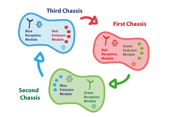
First Chassis: inRED-outGREEN
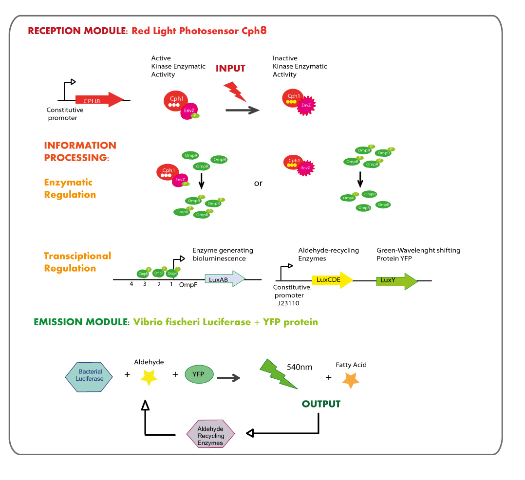
First Chassis: Red Light reception module coupled to Green Light emitter module.
Reception module: Red Light Photosensor cph8
OBJECTIVES
The main goal was the construction of a red light receptor able to indirectly trigger a transcriptional response that in our system corresponds to the expression of luxAB genes (Vibrio fischeri Luciferase).
METHODOLOGY
The red light receptor would be the chimeric protein Cph8(Cph1-EnvZ fusion). Exposure to red light inhibits the activity of the EnvZ histidine kinase domain. When active (in the dark) EnvZ phosphorylates endogenous OmpR, a transcription factor which activates transcription from the OmpC promoter and represses transcription from the OmpF promoter. While under light EnvZ would not phosphorilate OmpR, and OmpF promoter would not be repressed. In order to generate the transcriptional response of the luxAB genes in a light dependent manner, they were coupled to OmpF promoter.
This module of red light reception must be used in E.coli deficient in natural EnvZ to avoid cross-talk in the response.
Cph8 is into bio-brick BBa_I15010, however Cph8 needs another two proteins in order to reach its functional conformation and light sensitivity, these proteins are PcyA and Ho1 and they are coded in bio-brick BBa_K098010. There is another bio-brick which is composed of these two bio-bricks, it is called BBa_M30109.
The experimental strategy used consisted in the extraction of the aforementioned biobricks from the iGEM DNA distribution.
RESULTS
Even it was tried to get BBa_M30109 in the first place and then BBa_K098010 and BBa_I15010 from iGEM kit plate, we could not get those bio-bricks due to issues with DNA submission from iGEM kit plate.
Emission module: LuxAB luciferase from vibrio fischeri plus YFP protein
OBJECTIVES
- The final aim was the construction of the blue light emission bacterial luciferase (LuxAB)from Vibrio fischeri.
The structure of the device was designed as follows:
- Design LuxY biobrick, send to synthesize and transfer the construction from Mr. Gene plasmid to pSB1C3 DNA submission backbone.
- To test that the device works as expected.
Luciferase coded by luxA and luxB needs a substrate (an aldehyde synthesized by enzymes into the lux operon), in the project it was decided to add the aldehyde to the reaction in an exogenous way. So the biobrick to synthesize the aldehyde was not designed.
METHODOLOGY
The lux operon
Vibrio fischeri’s lux operon is composed of several genes, all of them involved in bioluminescence and its regulation.
This is the structure of Vibrio fischeri’s lux operon:
As it is shown in the diagram luxA and luxB genes, those coding for the luciferase, are placed together into the operon so the strategy was amplify them by means of PCR and then ligate PCR product with a strong constitutive promoter; the exogenously aldehyde added to the strain containing luxAB genes would be enough to trigger the luminescence reaction.
In the first place, we decided to purify genomic DNA from Vibrio fischeri strain MJ11 and then make a PCR with the following primers designed to extract luxAB region:
- Forward primer:Standard iGEM prefix+RBS+Coding Region
CGG AAT TCG CGG CCG CTT CTAG AGGA A ACA GCT ATG AAG TTT GGA AAT ATT TGT TTT TCG TAT CAA CC
- Reverse primer: Standard iGEM suffix+Coding Region
CTG CAG CGG CCG CTA CTA GTA TTA TTA GGG TAG ATT CTT TTC AAT TTT TTG GTT CAA C
YFP protein (LuxY)
LuxY is a gene coding for YFP, a protein that shifts the light emission wavelength of Vibrio fischeri’s luciferase from 484nm (blue) to 534nm (green - yellow); because our system needed a green or yellow emission module we looked in the literature for a protein capable to generate this phenotype.
The sequence was taken from the article published by Thomas O, et al., and then the sequence was synthesized by Mr.gene.
This is the composition of the synthesized sequence, “Gene” stands only for luxY coding region.
Preffix+ Promoter + RBS + Gene + Double Terminator + Suffix
See [http://partsregistry.org/wiki/index.php?title=Part:BBa_K360100 LuxY(BBa_K360100)] annotation at the registry for more details.
RESULTS
We tried to get luxAB from V.fischeri's genome and then make a bio-brick with these genes, although we did not have many problems getting luxAB genes from V.fischeri's genome with a PCR approach, ligations and the following transformations never worked although we tried with several plasmids (see Augusto's results).
However our collaborator, Cambridge University sent us a plasmid with luxABCDE under PBAD promoter so E.coli tranformated with this plasmid and grown in arabinose media showed a blue glowing phenotype.
We cotransformated luxABCDE with luxY and the cotransformation was successful although we have not been able to characterize it yet, the experiments are still in process.
REFERENCES
Thomas O. Baldwin, Mary L. Treat, S. Colette Daubner(1990).Cloning and expression of the luxY gene from Vibrio fischeri strain Y-1 in Escherichia coli and complete amino acid sequence of the yellow fluorescent protein.
Biochemistry 29 (23), 5509-5515.
Second Chassis:inGREEN-outBLUE

Second Chassis: Green Light reception module coupled to Blue Light emitter module.
Reception module: Green Light cianobacterial Photosensor CcaS/CcaR
OBJECTIVES
- Design and construction of the green ligth receptor.
- Expression of accesory genes for PCB creation, Ho1 & pcyA, in order to make the photosensor sensitive to light.
- Demonstrate the transcriptional regulation directed by the Green receptor with a GFP reporter.
METHODOLOGY
Green reception is composed of a two-component system. The green light sensing agent CcaS, that is a histidine kinase that phosphorylates the transcription factor CcaR, it shows greater affinity for DNA when is phosphorylated. This two-component system has been recently described in Synechocystis sp. PCC 6803, and due to the homology relationship with the EnvZ-OmpR system, it might possibly be functional in E.coli.
The strategy used was obtaining the sequences of the green light receptor (ccaS),transcriptional factor (ccaR) and DNA regulated region from Synechocystis sp. PCC6803, reported in Yuu Hirose, et al. Then these were sent to synthezise.
The DNA regulated region by CCaR would be ligated to the GFP protein, to analyze the activity of the photosensor.
RESULTS
Edinburgh team sent us plasmid with accesory genes for PCB creation because we could not get them from the existing biobrick BBa_K098010, which is compatible with the red reception module.
CcaR and CcaS were ligated to a weak constitutive promoter (J23117). Activity confirmation is still in progress.
Emission module: LuxAB luciferase from vibrio fischeri plus Lumazine protein
OBJECTIVES
- Obtain LuxAB genes from Vibrio fischeri.
- Design Lumazine biobrick, send to synthesize and transfer the construction from Mr. Gene plasmid to pSB1C3 DNA submission backbone.
- To test that the device works as expected. This characterization will test if Lumazine protein can also be functional working with the Vibrio fischeri luciferase, instead of its native interacting luciferase from Photobacterium phosphoreum.
METHODOLOGY
Lux operon
The strategy to obtain LuxAB genes from Vibrio fischeri was the same working with the green light emission module.
Lumazine
Lumazine protein of Photobacterium phosphoreum (lumP) is a small protein which shifts the wavelength of light emitted by the P.phosphoreum luciferase LuxAB from 495 nm to about 475 nm. It was used to tune the blue light emission wavelength towards another one closer to that of LovTAP system reception.
A version of the lumazine biobrick (BBa_K216007) was sent to us by Edinburgh Team, due to this construction hadn't been tested we decided to synthesize it, in order to avoid unexpected results for possible errors in the already assembled biobrick from Edinburgh.
This is the composition of the synthesized sequence, “Gene” stands only for lumazine coding region.
Preffix+ Promoter + RBS + Gene + Double Terminator + Suffix
See [http://partsregistry.org/wiki/index.php?title=Part:BBa_K360122 Lumazine (BBa_K360122)] annotation at the registry for more details.
RESULTS
In order to test if lumazine protein is working correctly, shifting the emission spectrum from Vibrio fischeri luciferase to more blue light output, co-transformation of the plasmid from Mr. gene harboring the Lumazine gene with the plasmid sent by Cambridge team containing the Vibrio Fischeri luciferase with the substrate generating and recycling pathway (luxABCDE) was successfully made, but the blue shifting glowing phenotype was not obtained, it was still green-blue. It is possible that the wavelength shift had done correctly but was not visible to naked eye due to the change is minuscule (495 nm to ~ 475 nm). So, it was required the usage of a sensible measurement device to detect it.
A first measurement was done with a spectrophotometer but it didn’t detect any RLU (relative light emission unit), even the bioluminescence was visible to naked eye in the dark room.
A second attempt will be using a CCD camera that is expected to have the necessary sensitivity to detect bioluminescence and measure the light emission spectrum.
REFERENCES
Yuu Hirose, Takashi Shimada, et al., (2008) Cyanobacteriochrome CcaS is the green light receptor that induces the expression of phycobilisome linker protein. Proceedings of the National Academy of Sciences, 105(28): 9528–9533.
O'Kane, D.J., Woodward, B., Lee, J., and Prasher, D.C. 1990. Borrowed proteins in bacterial bioluminescence. Proc. Natl. Acad. Sci. USA 88, 1100-1104.
Lee, J., Wang, Y., and Gibson, B.G. 1991. Electronic excitation transfer in the complex of lumazine protein with bacterial bioluminescence intermediates. Biochemistry 30, 6825-6835.
Third Chassis:inBLUE-outRED
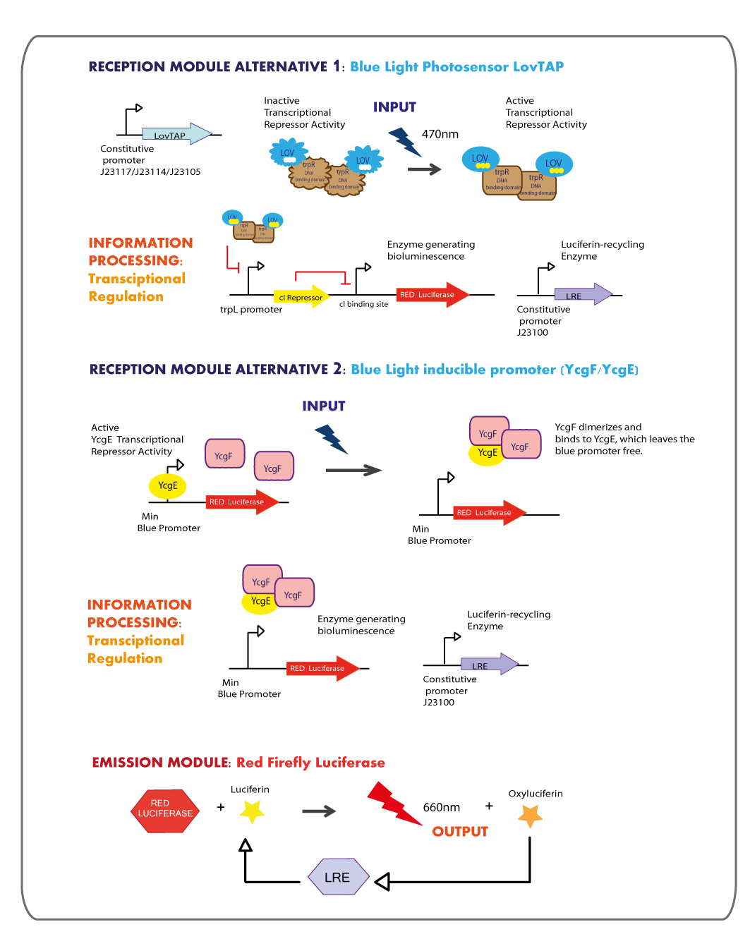
Third Chassis: Blue Light reception module coupled to Red Light emitter module.
Reception module: Blue Light Photosensor LovTAP and blue light inducible promoter
Working in this chassis, we decided to use as blue light receptors: LovTAP photosensor and the native blue light inducible promoter from E.coli.
LOVTAP
OBJECTIVES
- Construct an improved version of the LovTAP photosensor device under the regulation of different constitutive promoters, due to the previous version of LovTAP designed by 2009 Lausanne team didn´t have a differential behavior under the inverting regulator sensitive to LacI and CAP protein, their results showed that the expression levels of LovTAP didn’t show differences to the induction with IPTG. As well, we included a punctual mutation to change the ILE427 by a PHE427, as was proposed by the model results of the team iGEM09_EPF-Lausanne. With this mutation LovTAP should react faster and the conformational change should be more stable (the protein stays in the active form for longer, under light induction).
- Transfer the plasmid with the LovTAP synthesised gene from Mr. Gene Plasmid to pSB1C3 DNA submission backbone and ligate the construction to different weak constitutive promoters.
- Characterize LovTAP reporter systems, both repressor and activator activity.
The structure of the device is designed as follows:
METHODOLOGY
LovTAP design
We decided to synthesize the LovTAP photosensor that in comparison with the Part:BBa_K191003 that is already at the registry, has the following differences:
1. The 2 PstI restriction sites were removed from the coding region of LovTAP.
2. We included a punctual mutation to change the ILE427 by a PHE427, as was proposed by the model results of the team iGEM09_EPF-Lausanne [2]. With this mutation LovTAP should stay in the active form for longer, under light induction.
3. The part does not include a promoter.
4. The RBS was changed from a strong (Part: BBa_B0030) to a medium strength (Part:BBa_B0032).
5. The stop codon tga was changed for two taa.
For more details visit our team [http://partsregistry.org/wiki/index.php?title=Part:BBa_K360121 LovTAP -Part:BBa_K360121-] entry at the registry page.
E.coli Strain Mutant
As the transcriptional response regulated by LovTAP might also be generated by the trpR repressor in E.coli in tryptophan rich conditions , we looked for an Escherichia coli strain mutant in trpR to avoid the cross-talk of the endogenous function of this gene with our system.
After a careful look at the literature, we found that Dr. Charles Yanofsky had the mutant, so we sent him an e-mail, asking him to provide us the mutant.
The features of the mutant are:
1.Identification number: CY15001
2.Sex(Hfr,F+,F-,or F'): F-
5 Mutations:
•lamda- (lambda lysogen deletion)
•IN(rrnD-rrnE)1 (Inverts the region between rrnD and rrnE)
•rph-1 (RNase PH )
•tnaA5 (tryptophanase)
•trpR55 (repressor trpR)
LovTAP expression Levels
We got in touch with Dr. Devin Strickland the designer of LovTAP, in order to get some advices. Analyzing some experimental results reported in his dissertation and in the published paper : Light-activated DNA binding in a designed allosteric protein, it seems that at high expression levels of LovTAP, the behavior in the dark versus the light state is the same. So that, the regulation by light becomes not functional, thus we planned to test LovTAP under three different weak constitutive promoters (J23117,J23114 and J23105), expecting that it works well.
trpL promoter
The LovTAP system is composed of two modules, the light-sensitive input module is the LOV2 domain of Avena sativa phototropin 1 (AsLOV2). LOV domains absorb light through a flavin cofactor, photochemically form a covalent bond between the chromophore and a cysteine residue in the protein. The output module is the DNA binding domain of the bacterial transcription factor trp repressor (TrpR). So that, LovTAP activated can bind its operator DNA as a homodimer thus repressing transcription.
The DNA operator region where trp repressor binds was annotated wrongly in the 2009 EPF-Lausanne’s wiki as trpO promoter, but when searching for it in RegulonDB a very well annotated Escherichia coli transcriptional regulation data base, we found that the actually region where trp repressor binds is trpL promoter not trpO.
Knowing that we synthesized only trpLp’s functional elements as an oligonucleotide to introduce by PCR into a selected plasmid as follows:
Primer trpL reverse (5'->3'): NheI site + trpL promoter + XbaI site + EcoRI site:
TTGCTAGCGTGAACTTGCGTACTAGTTAACTAGTTCGATGATTAATTGTCAACAGCCTCTAGAAGCGGCCGCGAATTC
The primer is the reverse complementary of that sequence so we can use it as a reverse primer, which we used along with a suffix forward to introduce the trpL promoter into pSB1C3 plasmid by PCR.
LovTAP Reporter systems
As we are interested in characterize LovTAP activator and repressor activity. We have designed the following constructions.
- LovTAP repressor activity: Reporter system
1.trpL promoter fused to GFP protein:Part:BBa_E0240
2.trpL promoter fused to RFP protein: Part: BBa_E1010
- LovTAP activator activity: Reporter system
trpL promoter fused to lambda Repressor cI: Part:BBa_P0451 + Part:BBa_K098991 regulating GFP protein:Part:BBa_E0240.
Characterising LovTAP
Once LovTAP with the three weak constitutive promoters (J23117,123114 and J23105) and strong promoter (J23102) was correctly obtained in plasmid psb3k3, and the reporter system trpL+RFP was also finished by our team in plasmid psb1c3 , we started the co-transformation procedure in order to have the whole system inside the cells both trpR wild type and trpR mutant. Besides, we also receive the trpL+RFP construction in plasmid pSB1A2 from Lausanne team that was kindly sent it by Edinburgh team, because we didn’t get any response from the members of Lausanne team to provide us with their reporter systems. We are using both our trpL-RFP reporter system and the Lausanne system as a reference, expecting to obtain the similar results. The difference between the reporter systems is that ours doesn’t have the double terminator.
In order to test if LovTAP works correctly we implemented two protocols: the qualitative and the quantitative approach. With the qualitative approach we only want to observe and compare the RFP production in the cells exposed to light vs dark conditions, both in wild type and trpR mutant strains. What we are analyzing is the repressor activity of LovTAP, thus under light condition- when LovTAP repressor activity is activated, we expect to observe a lower level of RFP in comparison to the cells maintained in the dark state.
Considerations to take into account:
- The RFP protein doesn’t include a degradation tag so the time required to observe a clear difference between light and dark states will be long, because although LovTAP starts to repress, the RFP produced previously by the cells will be still present.
- The plasmid in which LovTAP is being express is Psb3k3 with a copy number around 20 to 30, trpL + RFP construction is inside plasmids psb1c3 and pSB1A2 both are high copy number plasmids -100 to 300 per cell-. So there are many trpL binding sites that should be repressed by LovTAP. The ideal condition for this experiment would be to have LovTAP and trpL+RFP constructions inside the same plasmid.
- Using the LovTAP constructions fused to promoters with different strength, we can test at what levels of expression, the LovTAP light regulation is better. We already know that under high expression levels of LovTAP, trpL promoter is repressed even in dark. To test this scenario we used J23102 promoter.
Qualitative experiment
Experimental procedure
1.Co-transform the cells using 5 microliters of each plasmid in the trpR mutant and in the wild type strains.
The samples used are:
- Our trpL+RFP reporter system plus:
J23102+LovTAP.
J23117+LovTAP.
J23114+LovTAP.
J23105+LovTAP.
- Lausanne trpL+RFP reporter system plus:
J23117+LovTAP.
J23114+LovTAP.
J23105+LovTAP.
2.Grow up the transformed cells overnight (~15hrs) in 5ml of LB medium at 37°C with spinning at 250rpm, with the respective antibiotics (Kanamicyn and chloramphenicol/ Kanamicyn and ampicillin ) in dark conditions.
3. Take 1 mL of broth and transfer it into 5 ml of fresh LB medium with antibiotics.
4. Incubate the cells in the two different conditions: the blue light and dark states for ~ 13 hrs.
Blue-Light samples were kept in the incubator covered in aluminium foil with 4 leds inside. The samples in dark conditions were maintained in the non-light devices that were constructed with bottles and newspaper.
5. Spin down the cultures and compare the RFP pellets obtained under blue-light vs. dark condition, and wild type samples vs. mutant samples.
Results
Only one colony of each co-transformation was used along the experiment and was tested under light and dark conditions.
In a first approach we observed that WT and trpR mutant cells co-transformed with LovTAP under J23102 promoter, grew in dark and light produced very low levels of RFP protein in comparison with the control sample (Wild type cells with only the reporter construction, trpL+RFP). So, it seems that we are observing the expected behavior under high expression levels of LovTAP. However we couldn’t notice a difference between dark and light conditions.
With this previous result we decided to continue the co-transformations procedure without considering the LovTAP construction under J23102 promoter.
Using LovTAP with promoters J23105, J23114 and J23117 (in order of high to lower strength) , we obtained the following pellets that are show in the next images:
- Samples with our trpL+RFP reporter.
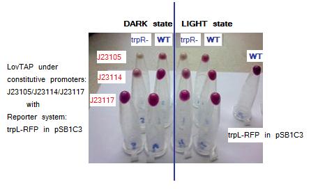
Testing LovTAP with our trpL+RFP reporter system in plasmid pSB1C3. The figure shows the pellets obtained from the cellular cultures. The non aligned tube at the left is a sample of WT cells harboring only our trpL+RFP construction.
Samples description is detailed here:
Rows listed from top to bottom and Columns from left to right.
Row, Column. LovTAP promoter, Strain phenotype, Condition
1,1.J23105,trpR mutant,Dark
1,2.J23105,Wild type,Dark
1,3.J23105,trpR mutant,Blue Light
1,4.J23105,Wild type,Blue Light
2,1.J23114,trpR mutant,Dark
2,2.J23114,Wild type,Dark
2,3.J23114,trpR mutant,Blue Light
2,4.J23114,Wild type,Blue Light
3,1.J23117,trpR mutant,Dark
3,2.J23117,Wild type,Dark
3,3.J23117,trpR mutant,Blue Light
3,4.J23117,Wild type,Blue Light
- Samples with Lausanne trpL+RFP reporter.
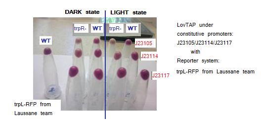
Testing LovTAP with Lausanne trpL+RFP reporter system in plasmid pSB1A2. The figure shows the pellets obtained from the cellular cultures. The non aligned tube at the right is a sample of WT cells harboring only trpL+RFP from Lausanne team construction.
Samples description is detailed here:
Rows listed from top to bottom and Columns from left to right.
Row, Column. LovTAP promoter, Strain phenotype, Condition
1,1.J23105,trpR mutant,Dark
1,2.J23105,Wild type,Dark
1,3.J23105,trpR mutant,Blue Light
1,4.J23105,Wild type,Blue Light
2,1.J23114,trpR mutant,Dark
2,2.J23114,Wild type,Dark
2,3.J23114,trpR mutant,Blue Light
2,4.J23114,Wild type,Blue Light
3,1.J23117,trpR mutant,Dark
3,2.J23117,Wild type,Dark
3,3.J23117,trpR mutant,Blue Light
3,4.J23117,Wild type,Blue Light
According to the images trpR mutants seem to have a lower RFP expression levels vs WT both in dark and light conditions. This a surprising result because we expected that showed higher levels than WT as they don’t have the possible crass-talk with trpR native E.coli repressor. Maybe there is another process of trpL repression that we are not taking into account independent to LovTAP and trpR.
Both trpL-RFP reporter systems give similar results. Comparing blue-light vs dark exposed samples there seems to be a small difference visible by naked-eye, with higher levels of RFP protein in dark state samples. Maybe the small difference observed between light and dark conditions is because LovTAP protein levels are very low to considerably repress the trpL promoter. As well, the long half-life of the RFP protein could be masking a significant difference between both states.
Although these results not formally demostrate that the LovTAP repression is light dependent, it seems that in cells co-transformed with LovTAP versus those transformed only with the trpL-RFP system, there are lower levels of RFP.
Another interesting pattern observed in the samples, is that there are lower levels of RFP as the promoter strength that regulates LovTAP increases, thus suggesting that there is a gradient of repression depending on the LovTAP concentration.
These results suggest that possibly LovTAP is working well, however as this experiment is totally qualitative we must improve it taking into account the optical density of the samples, because our observations could be due to the presence of different number of cells in each sample.
Quantitative experiment
With the aim to have a better characterization of LovTAP, we designed a new protocol considering the methodology describe by Jason R Kelly in the article “Measuring the activity of Bio-brick promoters using an in vivo reference standard”, we include some changes that are detailed below.
We decided to start the protocol under blue light conditions to test the dark state, expecting that in dark exposed samples the RFP levels increase in comparison with those samples that are always under blue light. We did this in order to face better the issue of the long half life of the RFP due to it doesn’t have a degradation tag.
Only one colony of each co-transformation was used along the experiment and was tested under light and dark conditions.
1.Co-transform the cells using 5 micro liters of each plasmid in the trpR mutant and in the wild type strains.
J23117/ 123114 / J23105 LovTAP + our trpL+RFP reporter system.
J23117/ 123114 / J23105 LovTAP + Lausanne trpL+RFP reporter system.
2.Grow up the transformed cells for ~20 hrs in 5ml of LB medium at 37°C with spinning at 250rpm, with the respective antibiotics (Kanamicyn and chloramphenicol/ Kanamicyn and ampicillin ) in Blue-light conditions.
3. Dilute the cultures to 1:100 into 5ml of fresh LB media with antibiotics.
4. Grow the cells for 4 hours at 37°C with spinning at 250rpm in Blue-light conditions.
5. Measure the optical density OD600 of 500 microliters of each culture and dilute them to an ODE of 0.15.
6. Transfer three 200 microliters aliquots from each culture into a flat-bottomed 96 well plate.
Samples were loaded in the plate as is shown in the next picture:
7. Make an initial measurement of OD and RLU of the plate.
8. Using the light emission device constructed to illuminate each well of the plate with one led. Keep the plate
at room temperature during 10 hrs under the desired light and dark conditions.
9. Make a second measurement of OD and RLU of the plate.
10. Compare initial data with the second measurement.
Results
We had problems during the development of the protocol in the steps of OD measurements, and unfourtunately the
initial data before the treatment of the plate with light and dark conditions were unsaved. So we couldn't compare the differences before and after the light and dark exposition of the samples in the plate.
Conclusions
According to the aforementioned results, we think that LovTAP could possibly work well. However we have to improve the characterization protocols in order to support with enough evidence this conclusion.
We also think that using other reporter system to describe the transcriptional activation activity of LovTAP using a cascade of double repression, might generate better results. So we will test LovTAP behavior with the cI inverter.
YcgF/YcgE BLUE RECEPTION SYSTEM
OBJECTIVES
The main goal for this section of the project was to implement a system for blue light
reception using the YcgF/YcgE sytem, naturally present in certain strains of Escherichia
coli.
This reception system would be coupled both to a reporter gene (i.e. GFP) and, for the
purposes of our project, a luciferase gene.
METHODOLOGY
We used a modified version of the YcgF/YcgE system for blue light reception (previously
reported by the K.U. Leuven 2009 Team), the modification consists in the reduction of the
promoter region to 50 bp.
Originally, we tried to amplify the complete promoter region BBa_238013 (86 bp) from
genomic DNA of E. coli K12 by PCR but we failed in several trials. So we decided to
synthesize the promoter in a primer and then insert it into pSB4A5 by PCR. Because of
lenght limitations in primer synthesis we reduced the promoter region to 50 bp.
The reduced promoter retains the fundamental parts of the original one, these are the -35
and -10 box, the spacer between them, the inverted repeat 1 and 2 (inverted regions are
the binding sites for the YcgE repressor) and the transcription start site. We registered this
Minimum Blue Light Receptor Promoter as BBa_K360041.
In order to test the functionality of our Minimum Blue Promoter we succesfully ligated it to
our Strong RBS BBa_K360031 and the GFP BBa_E0040.
Emission module: Red Firefly Luciferase
The red light emitter system that we decided to use is the firefly luciferase, this luciferase usually emits green light but with a punctual mutation we can shift the emission spectrum from green to red.
OBJECTIVES
- The final aim was the construction of the red light emission device, using the promoter region regulated by LovTAP with the red light emitting luciferase coupled to the Luciferin Regenerating Enzyme (LRE). The structure of the device is designed as follows:

- Design LRE biobrick and transfer the plasmid with the synthesised gene from Mr. Gene Plasmid to pSB1C3 DNA submission backbone and assemble it to a constitutive promoter.
- To test that the device works as expected.
METHODOLOGY
Mutated Firefly Luciferase
The original intention was to use the Photinus pyralis luciferase biobrick (BBa_I712019) as a base and to increase its efficiency by using the primer BBa_K360114 (as registered) due to previous design notes as referred in the part design section of this briobrick. After achieving this, a punctual mutation S284T (also known as S851T) was induced to change its emission spectrum from green to red by means of a PCR with special primers (which are also referred in the biobrick part design). The biobrick name is BBa_K360115; unfortunately, we were never able to find out why it was not functional.
Click Beetle Luciferase
By the middle of the summer, we decided to try the luciferase from another organism: Click Beetle, specifically the Promega Chroma-Luc™ Reporter Vectors pCBG99-Basic Vector Restriction Sites and the pCBR-Basic Vector Restriction Sites, where the first one has a green emission and the second one red. The intention was to work with these vectors as a means of having a previously-known-to-be functional luciferase, so that once the LRE biobrick was ready, characterization could be feasible. The first step was to extract the coding sequence of the luciferases from these vectors by means of PCR and also to standardize them by adding the prefix and suffix with the following primers:
Forward Click Beetle luciferase
GAATTCGCGGCCGCTTCTAGAGATTAAAGAGGAGAAAATGGTGAAGCGTGAGAAAAAT
Reverse Click Beetle luciferase
CTGCAGCGGCCGCTACTAGTATTATTAACCGCCGGCCTTCT
The second step was to ligate it into the BBa_J61002 plasmid with a J23101 promoter, and to transform it, having as an output several colonies which were then grown overnight to check whether the luciferases showed any brightness. The protocol followed for the assay is mentioned in BBa_K216015 biobrick, in the Experience part. In this first assay, no luminometer was used; so eventhough we added 1μL of 100mM luciferin and waited in the dark room for ~30min taking pictures with a SLR camera with high ISO (~400), for about 30secs to 1 min exposure, nothing was observed.
After the initial disappointment, Mariana talked to Cambridge team and they help us ever since then by sending us some of their constructions (BBa_K325909, BBa_K325109, BBa_K325209, and 2 other biobricks).
LRE design
Luciferin Regenerating Enzyme (LRE) was first reported by Gomi, K. and Kajiyama, N. [(2001) Oxyluciferin, a Luminescence Product of Firefly Luciferase, Is Enzymatically Regenerated into Luciferin. The Journal of Biological Chemistry, Vol. 276, No. 39. This enzyme proved to recycle the luciferase product oxyluciferin.
Our goal here was to couple both, luciferase and LRE, to be able to make the construction autonomous after the first and single input of luciferin. We sent to synthesize the LRE enzyme.
For more details see [http://partsregistry.org/wiki/index.php?title=Part:BBa_K360113 LRE -Part:BBa_K360113-] entry at the Registry page.

 "
"
