Team:WITS-South Africa/Gram positives
From 2010.igem.org
LauraMillroy (Talk | contribs) |
LauraMillroy (Talk | contribs) |
||
| Line 35: | Line 35: | ||
4. An unknown Lactobacillus strain | 4. An unknown Lactobacillus strain | ||
These bacteria have been selected because we would ideally like the chassis for our whole cell biosensor to be a gram positive bacterium. This being said; women have commensal lactobacillus gasseri bacteria within their vaginal mucosa. This bacterium provides the ideal target for genetically engineering ''L. gasseri'' to act as a proxy for infection and subsequently for amplifying the quorum signal and propagating the signal for infection across the population of bacterial cells. | These bacteria have been selected because we would ideally like the chassis for our whole cell biosensor to be a gram positive bacterium. This being said; women have commensal lactobacillus gasseri bacteria within their vaginal mucosa. This bacterium provides the ideal target for genetically engineering ''L. gasseri'' to act as a proxy for infection and subsequently for amplifying the quorum signal and propagating the signal for infection across the population of bacterial cells. | ||
| - | B. subtilis, S aureus and the LAB sp. Are also being used considering their gram positive properties. They are being tested to determine whether or not they could substitute L. gasseri as a chassis for our machine; only if Electroporation of L. gasseri fails. | + | ''B. subtilis'', ''S aureus'' and the LAB sp. Are also being used considering their gram positive properties. They are being tested to determine whether or not they could substitute ''L. gasseri'' as a chassis for our machine; only if Electroporation of ''L. gasseri'' fails. |
| Line 41: | Line 41: | ||
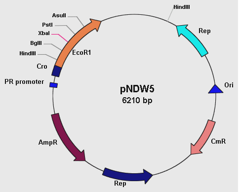
[[Image:PNDW5.png]] | [[Image:PNDW5.png]] | ||
| - | |||
| - | The pNDW5 plasmid is derived from a combination of two bacterial plasmids hence a shuttle vector; whereby one is gram positive and the other gram negative (S. aureus and E. coli respectively). | + | '''Figure 1: showing the pNDW5 plasmid map.''' |
| - | The S. aureus plasmid pC194 and E. coli plasmid pEcoR251 were combined to form the pNDW5 plasmid. This pNDW5 plasmid has a separate pair of Ori and Rep for gram positive and gram negative bacteria. This plasmid contains ampicillin and chloroamphenicol resistance marker genes; therefore ampicillin and chloroamphenicol resistant transformants with this plasmid can be selected. | + | |
| + | The pNDW5 plasmid is derived from a combination of two bacterial plasmids hence a shuttle vector; whereby one is gram positive and the other gram negative (''S. aureus'' and ''E. coli'' respectively). | ||
| + | The ''S. aureus'' plasmid pC194 and ''E. coli'' plasmid pEcoR251 were combined to form the pNDW5 plasmid. This pNDW5 plasmid has a separate pair of Ori and Rep for gram positive and gram negative bacteria. This plasmid contains ampicillin and chloroamphenicol resistance marker genes; therefore ampicillin and chloroamphenicol resistant transformants with this plasmid can be selected. | ||
The pNDW5 plasmid has an EcoRI suicide gene instead of a multiple cloning region; inside the gene are 4 unique restriction sites which allows for the positive selection of transformants with inserts. | The pNDW5 plasmid has an EcoRI suicide gene instead of a multiple cloning region; inside the gene are 4 unique restriction sites which allows for the positive selection of transformants with inserts. | ||
The plasmid has a PR promoter (phage λ promoter) whose original function is to drive the transcription of the Cro gene which allows for induction of phage from its lysogenic state in the E. coli cell. A large portion of this Cro gene has been removed which defers its functionality allowing the use of the PR promoter to drive expression of EcoRI without expressing the Cro gene. | The plasmid has a PR promoter (phage λ promoter) whose original function is to drive the transcription of the Cro gene which allows for induction of phage from its lysogenic state in the E. coli cell. A large portion of this Cro gene has been removed which defers its functionality allowing the use of the PR promoter to drive expression of EcoRI without expressing the Cro gene. | ||
| - | In pNDW5, a repressor can be used to stop transcription and expression of EcoRI suicide gene. The EcoRI suicide gene automatically kills the cell if no genes have been cloned. For testing the vector a mutant of this pNDW5 plasmid was used (denoted pNDW5*); which allowed testing for electro-transformation qualities in various potential gram positive bacteria (B. subtilis, L. gasseri, S. aureus and a LAB sp). | + | In pNDW5, a repressor can be used to stop transcription and expression of EcoRI suicide gene. The EcoRI suicide gene automatically kills the cell if no genes have been cloned. For testing the vector a mutant of this pNDW5 plasmid was used (denoted pNDW5*); which allowed testing for electro-transformation qualities in various potential gram positive bacteria (''B. subtilis, L. gasseri, S. aureus'' and a LAB sp). |
| Line 60: | Line 61: | ||
Electroporation of potential Gram positive bacteria | Electroporation of potential Gram positive bacteria | ||
| - | The protocols for electroporating all gram positive bacteria used in our project except L. gasseri can be obtained from http://openwetware.org/wiki/Main_Page | + | The protocols for electroporating all gram positive bacteria used in our project except ''L. gasseri'' can be obtained from http://openwetware.org/wiki/Main_Page |
General Electroporation protocol | General Electroporation protocol | ||
• Preparing electro-competent cells | • Preparing electro-competent cells | ||
| Line 88: | Line 89: | ||
The above protocol was administered for electroporating the unknown LAB sp. There were no changes made. | The above protocol was administered for electroporating the unknown LAB sp. There were no changes made. | ||
Electroporator parameters: 1.5 kV; 200 Ω; 25µF | Electroporator parameters: 1.5 kV; 200 Ω; 25µF | ||
| - | Results | + | |
| + | === Results === | ||
Upon completing Electroporation the following assessments were made: | Upon completing Electroporation the following assessments were made: | ||
The control and experimental plates had an equal number of colonies when chloroamphenicol (Cm) was used as a resistance marker at 20µg/ml. Hence secondary testing for the appropriate chloroamphenicol concentration was done. | The control and experimental plates had an equal number of colonies when chloroamphenicol (Cm) was used as a resistance marker at 20µg/ml. Hence secondary testing for the appropriate chloroamphenicol concentration was done. | ||
| + | |||
Table 1: shows LAB colonies in the control and experimental plates at increasing chloroamphenicol concentration. (Note: control plates are the LAB only; experiment plate has electroporated LAB). From these colonies further tests on transformants were done. | Table 1: shows LAB colonies in the control and experimental plates at increasing chloroamphenicol concentration. (Note: control plates are the LAB only; experiment plate has electroporated LAB). From these colonies further tests on transformants were done. | ||
Chloroamphenicol (Cm) | Chloroamphenicol (Cm) | ||
| Line 98: | Line 101: | ||
Cm 60 14 75 | Cm 60 14 75 | ||
Cm 70 57 45 | Cm 70 57 45 | ||
| - | Cm 80 | + | Cm 80 9 12 |
| - | Cm 90 0 | + | Cm 90 0 1 |
| - | Cm 100 | + | Cm 100 0 0 |
| - | + | At Cm concentrations of 60 µg/ml the ratio of experimental colonies to control colonies was approximately 5:1. To verify whether these colonies were real transformants plasmid extractions were attempted from these cells. However no plasmid could be detected. These results also suggest that this LAB strain has inherent resistance to chloroamphenicol therefore it cannot be used to determine whether pNDW5 would transform the LAB sp. | |
| - | + | ||
| - | Transformation efficiency | + | ==== Transformation efficiency ==== |
| - | In order to determine the success of transformation | + | In order to determine the success of transformation, the concentration of DNA used for the transformation would be determined. There are two methods to do this. The first is to analyze band intensities after gel electrophoresis in comparison to a control band whose DNA concentration is already known. The alternative method is to measure DNA concentration with a spectrophotometer at 260nm. Transformation efficiency would be expressed as the number of transformants per µg of DNA. |
| Line 117: | Line 120: | ||
=== Methods === | === Methods === | ||
| - | + | - A standard curve for analysing the growth characteristics of ''L. gasseri'' was undertaken | |
| - | + | - The protocol for electroporating ''L. gasseri'' was obtained from Nickoloff, J.A. (2007). Electroporation Protocols for Microorganisms: chapter 20- Transformation of Lactobacillus by Electroporation. Methods in Molecular Biology 47: 201- 208 | |
| - | Nickoloff, J.A. (2007). Electroporation Protocols for Microorganisms: chapter 20- Transformation of Lactobacillus by Electroporation. Methods in Molecular Biology 47: 201- 208 | + | |
| - | + | ||
| - | + | - The appropriate media was made; preparation of competent cells and Electroporation was done using the above mentioned protocol with minor adjustments. The most common marker genes applicable to LAB are genes causing resistance to erythromycin (Ery) and chloroamphenicol (Cm). | |
| + | |||
| + | - The concentrations used for the antibiotic plates were as follows according to the above protocol: | ||
• Erythromycin (Ery) 1 µg/ml | • Erythromycin (Ery) 1 µg/ml | ||
• Erythromycin 1 µg/ml and Chloroamphenicol 5 µg/ml | • Erythromycin 1 µg/ml and Chloroamphenicol 5 µg/ml | ||
• Chloroamphenicol (Cm) 5 µg/ml | • Chloroamphenicol (Cm) 5 µg/ml | ||
| - | + | - The media used, Electroporator parameters and incubation styles are different for ''L. gasseri'' | |
• Media = MRS for broth and agar; Sucrose Media | • Media = MRS for broth and agar; Sucrose Media | ||
• Electroporation buffer = MRSSM (MRS in Sucrose). | • Electroporation buffer = MRSSM (MRS in Sucrose). | ||
| Line 136: | Line 139: | ||
=== Results === | === Results === | ||
| - | The growth curve for L. gasseri is shown below: | + | The growth curve for ''L. gasseri'' is shown below: |
| - | Figure 1: | + | '''Figure 1: The cfu/ml of ''L. gasseri'' over a time period of 5 hours. The graph suggests an exponential increase in the colony forming units/ml after 2 hours of incubation.''' |
| - | Figure 2: | + | '''Figure 2: The O.D at wavelength of 600nm at time period of 6 hours. The O.D. was measured every hour. The gradual increase in O.D. is reflective of cell growth.''' |
| - | Table 2: Shows the Electroporation colony numbers for the pGK12, pNDW5 plasmid and the control plate at the different antibiotic concentrations | + | |
| + | |||
| + | '''Table 2: Shows the Electroporation colony numbers for the pGK12, pNDW5 plasmid and the control plate at the different antibiotic concentrations''' | ||
| + | |||
Plate type Ery (1µg/ml) Ery (1µg/ml) and Cm (5µg/ml) Cm (5µg/ml) | Plate type Ery (1µg/ml) Ery (1µg/ml) and Cm (5µg/ml) Cm (5µg/ml) | ||
| - | Control 3* 0 | + | Control 3* 0 0 |
| - | pGK12 1 5 | + | pGK12 1 5 0 |
| - | pNDW5* 80 | + | pNDW5* 80 0 0 |
| - | Note: the 3 colonies in the Ery 1µg/ml control plate were all contaminants and were not L. gasseri. | + | |
| - | + | ||
| - | The transformation efficiency could not be obtained for pGK12 because the original pGK12 DNA sample was either degraded or its concentration was very low. When the original pGK12 sample was transformed into E. coli; colony numbers were low (2 colonies) whereas a control plasmid (pACYC184) gave a high number of colonies. | + | '''Note:''' the 3 colonies in the Ery 1µg/ml control plate were all contaminants and were not ''L. gasseri''. |
| + | |||
| + | |||
| + | It can be seen from Table 2 that the pGK12 Ery (1µg/ml) plate; and Ery 1µg/ml Cm 5µg/ml plate had colonies that were possible transformants growing on them and so plasmid preps were undertaken. | ||
| + | The transformation efficiency could not be obtained for pGK12 because the original pGK12 DNA sample was either degraded or its concentration was very low. When the original pGK12 sample was transformed into ''E. coli''; colony numbers were low (2 colonies) whereas a control plasmid (pACYC184) gave a high number of colonies. | ||
pNDW5* shows 80 colonies on the erythromycin (1µg/ml) plate. This was obviously an error as pNDW5 does not confer resistance to erythromycin; therefore the colonies obtained shouldn’t have been observed here. | pNDW5* shows 80 colonies on the erythromycin (1µg/ml) plate. This was obviously an error as pNDW5 does not confer resistance to erythromycin; therefore the colonies obtained shouldn’t have been observed here. | ||
The transformation efficiency could not be measured here due to the inconsistency of the pNDW5* results. | The transformation efficiency could not be measured here due to the inconsistency of the pNDW5* results. | ||
| Line 159: | Line 169: | ||
=== Methods === | === Methods === | ||
| - | The general protocol obtained from http://openwetware.org/wiki/Main_Page was used to electroporate pNDW5* and pGK12 into B. subtilis and S. aureus. | + | The general protocol obtained from http://openwetware.org/wiki/Main_Page was used to electroporate pNDW5* and pGK12 into ''B. subtilis'' and ''S. aureus''. |
| + | |||
A few changes were made to the protocol: | A few changes were made to the protocol: | ||
• media used = LB | • media used = LB | ||
• Electroporation buffer = SHMG (sucrose, HEPES, magnesium chloride and glycerol) buffer | • Electroporation buffer = SHMG (sucrose, HEPES, magnesium chloride and glycerol) buffer | ||
• Incubation period = overnight for B. subtilis | • Incubation period = overnight for B. subtilis | ||
| - | Results | + | |
| - | Electroporation of S. aureus has been successful whereby optimization is being done for B. subtilis. | + | === Results === |
| + | Electroporation of ''S. aureus'' has been successful whereby optimization is being done for ''B. subtilis''. | ||
| Line 185: | Line 197: | ||
[[Image:Electroporation process.png]] | [[Image:Electroporation process.png]] | ||
| + | |||
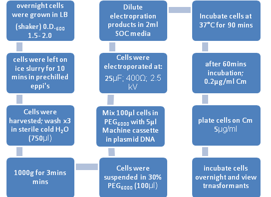
'''Figure 1: Flow diagram Representing Electroporation of ''B. subtilis''''' | '''Figure 1: Flow diagram Representing Electroporation of ''B. subtilis''''' | ||
| Line 227: | Line 240: | ||
== '''Test 5. Fluorescence analysis of electroporated constructs LacI, PlcR present in pNDW5 in the B. subtilis chassis''' == | == '''Test 5. Fluorescence analysis of electroporated constructs LacI, PlcR present in pNDW5 in the B. subtilis chassis''' == | ||
| - | Note: Optimization of the fluorescence analysis currently being undertaken as there are errors in experimental procedures | + | '''Note:''' Optimization of the fluorescence analysis currently being undertaken as there are errors in experimental procedures |
=== Methods === | === Methods === | ||
| Line 248: | Line 261: | ||
mCherry at 590nm and emits at 610nm | mCherry at 590nm and emits at 610nm | ||
| + | |||
==== The Preparation of Inducers ==== | ==== The Preparation of Inducers ==== | ||
| - | + | IPTG: | |
32mM stock was prepared and the final concentration used was 1mM. | 32mM stock was prepared and the final concentration used was 1mM. | ||
32µM stock was also prepared at a final concentration of 1µM. | 32µM stock was also prepared at a final concentration of 1µM. | ||
| - | + | ||
| - | Bacillus Cereus was grown in Brain Heart infusion broth at 37°C for 3 days and the supernatant was then used to induce PlcR promoter. However the concentration of PlcR-Pap R in the supernatant was unknown as there were limitations to the time available to assay the culture to determine how much of the Inducer was present in the culture. A 100x dilution of the supernatant was also prepared. | + | Supernatant derived from ''B. cereus'': |
| + | ''Bacillus Cereus'' was grown in Brain Heart infusion broth at 37°C for 3 days and the supernatant was then used to induce PlcR promoter. However the concentration of PlcR-Pap R in the supernatant was unknown as there were limitations to the time available to assay the culture to determine how much of the Inducer was present in the culture. A 100x dilution of the supernatant was also prepared. | ||
==== Preparation of Cell cultures ==== | ==== Preparation of Cell cultures ==== | ||
| Line 271: | Line 286: | ||
Note: | Note: | ||
| - | - | + | - Showing only final IPTG concentration of 1mM and undiluted Supernatant, |
| - | - The 100x diluted supernatant and 1µM IPTG are not shown and denoted with an X | + | - The 100x diluted supernatant and 1µM IPTG are not shown and denoted with an X |
| - | - Supernatant denoted *Sup | + | - Supernatant denoted *Sup |
| - | - Average values were taken and put in table I | + | - Average values were taken and put in table I |
Fluorescence absorbance values were recorded at an excitation wavelength of 595nm for mCherry; the emission wavelength used for graphs was 610nm for the same fluorescent protein | Fluorescence absorbance values were recorded at an excitation wavelength of 595nm for mCherry; the emission wavelength used for graphs was 610nm for the same fluorescent protein | ||
The only results recorded for Inducer concentrations were undiluted Supernatant and 1mM IPTG | The only results recorded for Inducer concentrations were undiluted Supernatant and 1mM IPTG | ||
| Line 295: | Line 310: | ||
---- | ---- | ||
| - | + | ||
[[Image:Fig 1.JPG]] | [[Image:Fig 1.JPG]] | ||
Revision as of 15:09, 26 October 2010

Gram Positive Bacteria
Introduction
We have been working on optimising a protocol for electro-transformations on several gram positive bacteria that can function as the chassis for our machine. Lange has been performing several test experiments by electroporating several potential gram positive bacteria (i.e. Bacillus subtilis; Lactobacillus gasseriand Staphylococcus aureus). This is being done in preparation for electroporation of the machine constructs into either one of these gram positive bacteria; depending on the most efficient bacteria we have to work with.
We are also testing the ability of transforming the above mentioned bacteria with two different shuttle-vector plasmids; namely: • pGK12 • pNDW5 Once we have established which plasmid is best to use for electroporation; the gene constructs will then be inserted into that plasmid and we will perform electroporations using that plasmid. Electro-transformation of the selected bacterium will be done with our machine constructs; and testing of transformants will be undertaken. Once this is achieved analysis of the machines’ functionality will be determined using fluorescence in situ hybridisation and other fluorescent techniques (i.e. fluorimetry).
We plan to achieve a high efficiency of gram positive transformation by optimizing relevant protocols for electroporation and fluorescence analysis.
Why Electroporation?
Electro-transformations are mostly used to transform bacteria using large amounts of plasmid DNA; this method involves the use of an electric pulse that creates temporary pores in the cell wall of bacteria allowing the bacteria to take up the plasmid. Initially this plasmid needs to be along the surface of the cell wall for instant incorporation of the plasmid into the bacterial cytoplasm when an electric pulse in administered. Protocols for electro-transforming different kinds of gram positive bacteria vary depending on the strain, or family of bacteria (i.e. Lactobacillus species have been shown to require different media for Electroporation).
Electro-transformation of potential Gram positive bacteria The Gram positive bacteria that are being tested are: 1. Bacillus subtilis 2. Lactobacillus gasseri 3. Staphyloccus aureus 4. An unknown Lactobacillus strain These bacteria have been selected because we would ideally like the chassis for our whole cell biosensor to be a gram positive bacterium. This being said; women have commensal lactobacillus gasseri bacteria within their vaginal mucosa. This bacterium provides the ideal target for genetically engineering L. gasseri to act as a proxy for infection and subsequently for amplifying the quorum signal and propagating the signal for infection across the population of bacterial cells. B. subtilis, S aureus and the LAB sp. Are also being used considering their gram positive properties. They are being tested to determine whether or not they could substitute L. gasseri as a chassis for our machine; only if Electroporation of L. gasseri fails.
pNDW5 Plasmid
Figure 1: showing the pNDW5 plasmid map.
The pNDW5 plasmid is derived from a combination of two bacterial plasmids hence a shuttle vector; whereby one is gram positive and the other gram negative (S. aureus and E. coli respectively). The S. aureus plasmid pC194 and E. coli plasmid pEcoR251 were combined to form the pNDW5 plasmid. This pNDW5 plasmid has a separate pair of Ori and Rep for gram positive and gram negative bacteria. This plasmid contains ampicillin and chloroamphenicol resistance marker genes; therefore ampicillin and chloroamphenicol resistant transformants with this plasmid can be selected. The pNDW5 plasmid has an EcoRI suicide gene instead of a multiple cloning region; inside the gene are 4 unique restriction sites which allows for the positive selection of transformants with inserts. The plasmid has a PR promoter (phage λ promoter) whose original function is to drive the transcription of the Cro gene which allows for induction of phage from its lysogenic state in the E. coli cell. A large portion of this Cro gene has been removed which defers its functionality allowing the use of the PR promoter to drive expression of EcoRI without expressing the Cro gene. In pNDW5, a repressor can be used to stop transcription and expression of EcoRI suicide gene. The EcoRI suicide gene automatically kills the cell if no genes have been cloned. For testing the vector a mutant of this pNDW5 plasmid was used (denoted pNDW5*); which allowed testing for electro-transformation qualities in various potential gram positive bacteria (B. subtilis, L. gasseri, S. aureus and a LAB sp).
pGK12 plasmid
The pGK12 plasmid is also a shuttle vector; it can be propagated in both Gram-positive and Gram-negative bacteria and it carries erythromycin and chloroamphenicol resistance markers. This plasmid has 3 restriction sites; HpaII, NdeI and BpmI.
What has been happening in the lab
Electroporation of potential Gram positive bacteria The protocols for electroporating all gram positive bacteria used in our project except L. gasseri can be obtained from http://openwetware.org/wiki/Main_Page General Electroporation protocol • Preparing electro-competent cells • Overnight culturing in Luria Broth (LB)* • Inoculate x100 dilution of culture into LB with 1.9% glycine • Incubate at 37°C • Measure 0.D. 600 (range 0.7) • Harvest cells (centrifuge) • Wash cells (x2) in Electroporation buffer • Harvest cells and suspend in 1/100 volume of Electroporation buffer • 50µl transformation • Electroporator parameters vary depending on strain • Inoculate in LB and incubate for 3hours at 37°C on a shaker • Plate in Luria agar and appropriate antibiotic plate (Note: LB* = media may vary depending on bacterial strain or species) The tests that I am currently performing are as follows:
Test 1. Electroporation of pNDW5* into a Lactobacillus sp.
Methods
The above protocol was administered for electroporating the unknown LAB sp. There were no changes made. Electroporator parameters: 1.5 kV; 200 Ω; 25µF
Results
Upon completing Electroporation the following assessments were made: The control and experimental plates had an equal number of colonies when chloroamphenicol (Cm) was used as a resistance marker at 20µg/ml. Hence secondary testing for the appropriate chloroamphenicol concentration was done.
Table 1: shows LAB colonies in the control and experimental plates at increasing chloroamphenicol concentration. (Note: control plates are the LAB only; experiment plate has electroporated LAB). From these colonies further tests on transformants were done. Chloroamphenicol (Cm) Concentration (µg/ml) Control plate colony county Experiment plate Colony count Cm 40 36 66 Cm 50 28 48 Cm 60 14 75 Cm 70 57 45 Cm 80 9 12 Cm 90 0 1 Cm 100 0 0
At Cm concentrations of 60 µg/ml the ratio of experimental colonies to control colonies was approximately 5:1. To verify whether these colonies were real transformants plasmid extractions were attempted from these cells. However no plasmid could be detected. These results also suggest that this LAB strain has inherent resistance to chloroamphenicol therefore it cannot be used to determine whether pNDW5 would transform the LAB sp.
Transformation efficiency
In order to determine the success of transformation, the concentration of DNA used for the transformation would be determined. There are two methods to do this. The first is to analyze band intensities after gel electrophoresis in comparison to a control band whose DNA concentration is already known. The alternative method is to measure DNA concentration with a spectrophotometer at 260nm. Transformation efficiency would be expressed as the number of transformants per µg of DNA.
Test 2. Electroporation of pNDW5* and pGK12 into L. gasseri
Methods
- A standard curve for analysing the growth characteristics of L. gasseri was undertaken
- The protocol for electroporating L. gasseri was obtained from Nickoloff, J.A. (2007). Electroporation Protocols for Microorganisms: chapter 20- Transformation of Lactobacillus by Electroporation. Methods in Molecular Biology 47: 201- 208
- The appropriate media was made; preparation of competent cells and Electroporation was done using the above mentioned protocol with minor adjustments. The most common marker genes applicable to LAB are genes causing resistance to erythromycin (Ery) and chloroamphenicol (Cm).
- The concentrations used for the antibiotic plates were as follows according to the above protocol: • Erythromycin (Ery) 1 µg/ml • Erythromycin 1 µg/ml and Chloroamphenicol 5 µg/ml • Chloroamphenicol (Cm) 5 µg/ml
- The media used, Electroporator parameters and incubation styles are different for L. gasseri • Media = MRS for broth and agar; Sucrose Media • Electroporation buffer = MRSSM (MRS in Sucrose). • Electroporator parameters: 1.5 kV; 800 Ω; 25µF • Growth = anaerobic chamber and not shaken
Results
The growth curve for L. gasseri is shown below:
Figure 1: The cfu/ml of L. gasseri over a time period of 5 hours. The graph suggests an exponential increase in the colony forming units/ml after 2 hours of incubation.
Figure 2: The O.D at wavelength of 600nm at time period of 6 hours. The O.D. was measured every hour. The gradual increase in O.D. is reflective of cell growth.
Table 2: Shows the Electroporation colony numbers for the pGK12, pNDW5 plasmid and the control plate at the different antibiotic concentrations
Plate type Ery (1µg/ml) Ery (1µg/ml) and Cm (5µg/ml) Cm (5µg/ml) Control 3* 0 0 pGK12 1 5 0 pNDW5* 80 0 0
Note: the 3 colonies in the Ery 1µg/ml control plate were all contaminants and were not L. gasseri.
It can be seen from Table 2 that the pGK12 Ery (1µg/ml) plate; and Ery 1µg/ml Cm 5µg/ml plate had colonies that were possible transformants growing on them and so plasmid preps were undertaken.
The transformation efficiency could not be obtained for pGK12 because the original pGK12 DNA sample was either degraded or its concentration was very low. When the original pGK12 sample was transformed into E. coli; colony numbers were low (2 colonies) whereas a control plasmid (pACYC184) gave a high number of colonies.
pNDW5* shows 80 colonies on the erythromycin (1µg/ml) plate. This was obviously an error as pNDW5 does not confer resistance to erythromycin; therefore the colonies obtained shouldn’t have been observed here.
The transformation efficiency could not be measured here due to the inconsistency of the pNDW5* results.
Test 3. Electroporation of pNDW5* and pGK12 into B. subtilis and S. aureus
Methods
The general protocol obtained from http://openwetware.org/wiki/Main_Page was used to electroporate pNDW5* and pGK12 into B. subtilis and S. aureus.
A few changes were made to the protocol: • media used = LB • Electroporation buffer = SHMG (sucrose, HEPES, magnesium chloride and glycerol) buffer • Incubation period = overnight for B. subtilis
Results
Electroporation of S. aureus has been successful whereby optimization is being done for B. subtilis.
Test 4 Electroporation of machine cassettes in B. subtilis
Introduction
Bacillus subtilis is a gram positive soil bacterium from the genus bacillus. It has proven highly useful to genetic manipulation, and has therefore become widely adopted as a model organism for laboratory studies. It is also heavily flagellated, which gives B. subtilis the ability to move quite quickly. In terms of popularity as a laboratory model organism this bacterium is often used as the Gram-positive equivalent of Escherichia coli, an extensively studied Gram-negative bacterium.
It has proved useful in electroporating our machine constructs and has yielded good electroporation efficiencies for Machine Intermediates 1 and 2. Lactodetect and Lactoreport have also been successfully electro-transformed into B. subtilis as numerous transformants were present from colony plate counts however no empirical data has been calculated for these constructs. It is no surprise therefore that we have chosen to work with this bacterium as a model organism as an alternative to L. gasseri as a chassis for our Lactoguard Machine.
Methods
The general electroporation protocol was followed with minor adjustments.
Figure 1: Flow diagram Representing Electroporation of B. subtilis
B. subtilis strains were grown overnight in LB broth at 37°C with vigorous aeration. The changes to the Electroporation protocol included:
1. SOC Broth= pulsed cells were diluted in 2ml of this broth(contains 2% tryptone, 0.5% yeast extract, 10mM NaCl, 2.5mM KCl, 10mM MgCl2, 10mM MgSO4, 20mM glucose) 2. 30% PEG6000 = Polyethyleneglycol (Electroporation medium) 3. De – ionised water for the washes.
Results
The following constructs were electroporated. - Machine Intermediate 1 (LacI/ AraC promoter – mCherry – tt) - Machine Intermediate 2 (PlcR promoter – mCherry – tt) - pNDW5* vector (no “machine” genetic information; control) - Lactodetect ( LacI/ AraC promoter – PlcR –PapR – Venus- tt) in pNDW5 - Lactoreport (PlcR promoter – PlcR-PapR- mCherry – PO Phage activator – tt – PO Phage promoter – E. chromi – SpooA – tt)
Mass calculation for machine 1 and 2 intermediates
Machine 1 intermediate DNA conc. = 52.2ng/µl; Machine 2 intermediate DNA conc. = 48.3ng/ml The volume used for electroporation was 5µl Hence: C = M / V whereby C is the concentration, M is mass and V is volume Mass of Machine 1 intermediate =C x V = 52.2ng/µl x 5µl = 261ng Mass of Machine 2 intermediate = C x V = 48.3ng/µl x 5µl = 241.5ng
Electroporation Efficiencies for Machine intermediate 1 and 2 in B. subtilis
Colonies from electroporation plates were counted and yielded the following: Machine 1 intermediate = 1300 transformants Machine 1 intermediate = 1300 colonies/261ng DNA = 1300/0.261µg DNA = 4980 colonies/ µg DNA
Machine 2 intermediate = 1400 transformants Machine 2 intermediate = 1400 colonies/241.5ng DNA = 1400/0.2415µg DNA = 5797 colonies/ µg DNA
pNDW5* = 0 transformants (No DNA control) The pNDW5* vector had no transformants as expected
Electroporation efficiencies were not calculated Lactodetect and Lactoreport
Test 5. Fluorescence analysis of electroporated constructs LacI, PlcR present in pNDW5 in the B. subtilis chassis
Note: Optimization of the fluorescence analysis currently being undertaken as there are errors in experimental procedures
Methods
For analysing the fluorescence capabilities of our constructs fluorimetry was used. A 96- well Bio-rad iMark Microplate reader was used to load samples of: • LacI with Inducer (IPTG), LacI without Inducer (no IPTG added) • PlcR with inducer (supernatant), PlcR without inducer (Supernatant) • pNDW5* plasmid not containing cloned constructs only • pNDW5* with Inducer (IPTG, Supernatant, in separate wells) • LB with Inducer (IPTG, Supernatant ,in separate wells) • LB only
Fluorescent protein in the constructs is mCherry 1. Machine 1 LacI (M1L1)
Image:1
2. Machine 1 PlcR (M1P2)
Image:2
mCherry at 590nm and emits at 610nm
The Preparation of Inducers
IPTG: 32mM stock was prepared and the final concentration used was 1mM. 32µM stock was also prepared at a final concentration of 1µM.
Supernatant derived from B. cereus: Bacillus Cereus was grown in Brain Heart infusion broth at 37°C for 3 days and the supernatant was then used to induce PlcR promoter. However the concentration of PlcR-Pap R in the supernatant was unknown as there were limitations to the time available to assay the culture to determine how much of the Inducer was present in the culture. A 100x dilution of the supernatant was also prepared.
Preparation of Cell cultures
• LacI in pNDW5; PlcR in PNDW5 and the PNDW5* plasmid colonies were grown in 1ml LB in the presence of Chloroamphenicol (Cm) 5µg/ml at 37°C overnight on a shaker. • Overnight cultures were resuspended and transferred to new eppi’s • These were spun down and the supernatant was removed • The cells were resuspended in 1ml LB and a 5µl Cm 5µg/ml • 100µl LB with Cm 5µg/ml were added to relevant wells • In the appropriate wells 1µl resuspended cells (LacI, PlcR or pNDW5*) were added • The cells were incubated for 2hours at 37°C on a shaker • The appropriate inducers were added to the relevant wells for their respective constructs • fluorescence was recorded every 5mins for 80 minutes using the Bio-rad iMark Microplate reader at 25°C
Illustration showing the arrangement of Cell cultures in the 96- well microtitre plate. The fluorescence analyses for these cultures were performed in triplicate and a mean value was used.
Table: I
Note: - Showing only final IPTG concentration of 1mM and undiluted Supernatant, - The 100x diluted supernatant and 1µM IPTG are not shown and denoted with an X - Supernatant denoted *Sup - Average values were taken and put in table I Fluorescence absorbance values were recorded at an excitation wavelength of 595nm for mCherry; the emission wavelength used for graphs was 610nm for the same fluorescent protein The only results recorded for Inducer concentrations were undiluted Supernatant and 1mM IPTG
Results
Table II: Average values for each triplicate experiment from the microtitre plate
Percentage Fluorescence To calculate the % Fluorescence emitted the following formula was used and the graphs correspond to the values calculated in Table II. The values used to calculate % Fluorescence are taken from Table I at each Time interval as follows:
% Fluorescence = [(x with Inducer - LB with Inducer)/(x - LB)] X 10
Whereby x denotes fluorescence from the construct (i.e. LacI, PlcR or pNDW5*) The percentage Fluorescence should give values in excess of 100%; which means that for a Fluorescence % of 100, the fluorescence of the construct with inducer and construct without inducer are equal, meaning that there was no increase in fluorescence upon addition of the inducer. Hence percentages greater than 100 mean that the inducer was able to increase the expression of the fluorescence gene. So we were looking to obtain values greater than 100% which suggests that the fluorescence produced by the machine can be regulated by adding an inducer which suggests functionality of the machine (i.e. Inducibility of the promoter) When values are less than 100, this could mean that the inducer is somehow interfering with the fluorescence however we don’t know how it would do this. When values are 1equal to 100 then it means that the inducer isn’t making any difference to the fluorescence.
Table III: Shows the % Fluorescence of LacI with respect (wrt) to IPTG and the Vector (pNDW5*), PlcR wrt Supernatant (Sup) and vector (pNDW5*), and the vector pNDW5* wrt the two inducers IPTG and Sup.
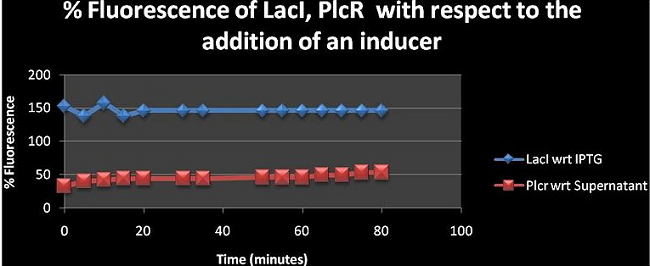
Figure 1: Shows the fluorescence percentage of LacI, PlcR with respect to (wrt) the addition of relevant inducers over a time period of 80 minutes. The % fluorescence was analysed at 5mins intervals. The figure shows the effect of adding the inducer has on fluorescence. LacI has a value greater than 100% suggesting that the inducer is contributing to the fluorescence emitted by the machine construct upon its addition. However, PlcR seems to have a percentage of less than 100 which could mean that the supernatant is diminishing the fluorescence of the PlcR construct see: (Table I for values of PlcR)
% Fluorescence = [(x with Inducer - LB with Inducer)/(x - LB)] X 100
[x = construct]
% Fluorescence (for time interval 80 mins) = [(0.08 −0.065) / (0.065 – 0.037)] × 100 = 53.6 %
Upon viewing this calculation one would assume that the PlcR inducer isn’t contributing to the fluorescence however the equation shows that 0.08 is the PlcR with inducer and 0.065 is the PlcR without inducer and these are considerably different. So one could also say that it’s the inducer that’s fluorescing however the supernatant from B. cereus hasn’t been analysed hence the properties of the supernatant solution are really unknown. The value for LB with supernatant is much larger than that of the LB only showing its contribution to the fluorescence reading. We do however hope that the solution contains the PlcR- pap R protein which acts as an inducer to the PlcR promoter thus triggering expression of mCherry (fluorescent protein used). The supernatant is not contributing to the induction of mCherry expression Binding Affinity of PlcR –Pap R (is this affecting fluoresecence of mCherry in the when bound to the Plcr promoter?)
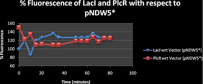
Figure 2: shows the % fluorescence of the constructs LacI and PlcR with respect to the vector (pNDW5*). The fluorescence was measured at 5minute intervals for 80 minutes.
% Fluorescence = [(x with Inducer - LB with Inducer)/(x - LB)] X 100
The results in figure 2 show % fluorescence greater than 100 for both LacI and PlcR. Hence the effect of having fluorescence genes in the plasmid is analysed here. Values greater than 100 show that the fluorescence observed is due to the fluorescence gene mCherry present in both constructs. . x with inducer = construct with inducer; whereas x = pNDW5* plasmid with inducer, LB = LB with inducer since hence x = pNDW5* plasmid with inducer. when the calculation is made it is observed that the % Fluorescence is due to the fluorescence gene present in the plasmid. Note: Fluorescence measurements are for constructs electroporated into the pNDW5* plasmid hence we measure construct fluorescence against pNDW5* plasmid only. Figure 3, 4, 5, 6 and 7 are derived from absolute mean values taken from table I. These figures are used to compare the similarities and differences between the curves of each construct over 80 minutes and are just additional diagrams for analysis.
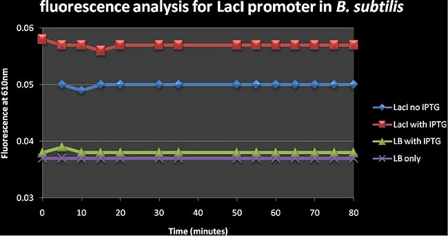
Figure 3: shows the absolute average fluorescence values for the LacI promoter over 80 minutes at 5 minute intervals. Upon visual inspection of figure 3, the difference between the LacI with IPTG and LacI no IPTG curves is greater than that of LB with IPTG and LB only curves; this suggests that IPTG has a greater effect on cells than just Luria broth. There is a slight increase in fluorescence from 0.05 to ±0.058 in the LacI constructs upon adding IPTG. The Fluorescence of LacI on IPTG is a lot higher than LB with IPTG and LB only which suggests that there is a lot of background expression occurring in the absence of an inducer; this is consistent with the notion that this LacI/AraC promoter has leaky expression.
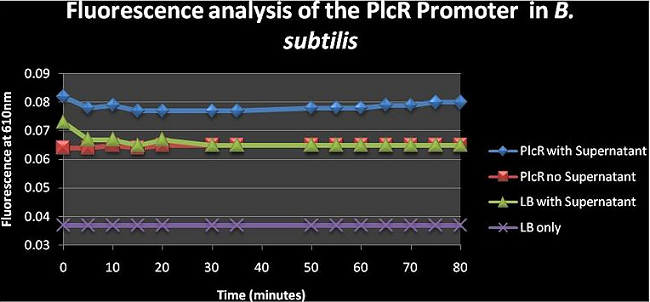
Figure 4: shows the absolute average fluorescence values for the PlcR promoter over 80 minutes at 5 minute intervals. The PlcR no supernatant curve is similar to the LB with supernatant curve meaning that the cells aren’t really able to express fluorescence genes without supernatant. It can also be seen that adding the supernatant to the cell cultures will increase fluorescence; but we can’t really say whether the fluorescence is due to the Fluorescence genes being expressed at higher rate or whether the increased fluorescence is from the supernatant itself as this was not assayed. The supernatant should have the PlcR- Pap R quorum genes which would bind to the PlcR promoter inducing transcription and expression of mCherry.
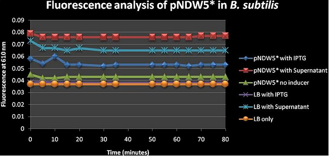
Figure 5: shows the absolute average fluorescence values for the pNDW5* plasmid over 80 minutes at 5 minute intervals. pNDW5* has no fluorescence genes inserted (i.e. low value pNDW5* on inducer) hence this figure shows us the effect of the inducers on the plasmid and allows us to determine the effect of the plasmid on the fluorescence in the presence of and inducer/without inducer (see figure 2). Figure 5 suggests that the supernatant induces more fluorescence than IPTG even when the plasmid has no fluorescent genes inserted. One can argue here and say that according to this figure; the inducer with the least fluorescence value is the better because it in itself has no contribution to fluorescence which would give false positives (more fluorescence than what is actually induced); so IPTG would be better. I do stress the fact that the supernatant properties are not fully known hence the fluorescence increase may be due to a factor arising from there.
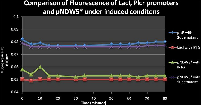
Figure 6: comparison of fluorescence of LacI, PlcR and pNDW5* under induced conditions using IPTG and a Supernatant from B. cereus. From figure 6 one can see that the pNDW5* vector with supernatant and PlcR with supernatant are similar; the difference between the LacI with IPTG and pNDW5* with IPTG is due to the fluorescence gene being in the plasmid for the LacI curve; which means that IPTG is not as effective as the supernatant in increasing construct fluorescence levels (PlcR, LacI only not pNDW5*)
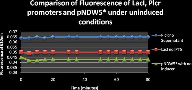
Figure 7: Compares the fluorescence of LacI, PlcR and pNDW5* under non-induced conditions over 80 minutes. PlcR levels remain constant throughout the entire duration and so does LacI. There is a trend that is observed though out figures 1-7. Most of these curves remain constant whereas only some fluctuate. This constant nature may be due to the two things. 1. The aeration in the wells is not that high due to the small size of the wells. Therefore the cells don’t grow as quickly as would normally do. 2. The temperature in the Bio- rad Microplate reader cannot be regulated and is constant at room temperature. Whereas the cells need to be kept at a temperature of 37°C and also need to be shaken for optimal growth
Therefore if one measures fluorescence at 5 minute intervals; you can’t really expect to observe changes in fluorescence because the cells aren’t growing quickly enough. This means that the cells aren’t metabolising at an optimal rate and hence fluorescence values are low. If you took readings every 3hours though, you may see greater differences in fluorescence values thus changing the observed nature of the curves. "
"
