Team:TU Munich/Project
From 2010.igem.org
Hartlmueller (Talk | contribs) (→toogle switch) |
(→Putting it all together: the switching process) |
||
| Line 78: | Line 78: | ||
===Putting it all together: the switching process=== | ===Putting it all together: the switching process=== | ||
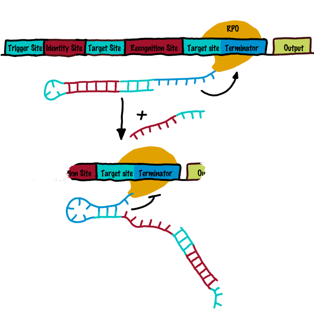
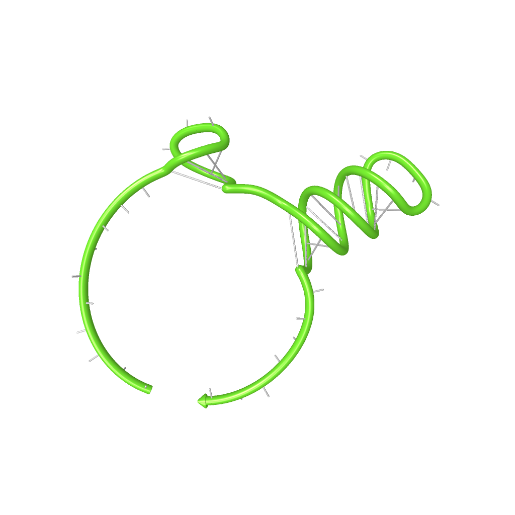
| - | Figure xxx illustrates the functional principle of the designed switch. The switch is implemented in the front a desired output. So in the ground state, transcription will be canceled by the formation of a RNA stem loop in the nascent RNA-chain, which then causes the RNA polymerase to stop transcription and fall off the DNA and no output RNA will be produced. | + | [[Image:projekt_bild_1.1.png|500px|thumb|left]] Figure xxx illustrates the functional principle of the designed switch. The switch is implemented in the front a desired output. So in the ground state, transcription will be canceled by the formation of a RNA stem loop in the nascent RNA-chain, which then causes the RNA polymerase to stop transcription and fall off the DNA and no output RNA will be produced. |
On the other hand, in the presence of a [[Team:TU_Munich/Project#signals, the inputs, transmitters and outputs of the bioLOGICS switch | signal]], this small functional RNA inhibits the stem loop formation by complementary base-pairing and hence avoids transcription termination. In detail, the <span style="color:red"> specificity unit </span> binds the <span style="color:lightblue"> recognition unit </span> and serves as [[Team:TU_Munich/Glossary#toehold|toehold]], which will thermodynamically allow the <span style="color:red"> trigger unit </span> to perform a [[Team:TU_Munich/Glossary#strand displacement|strand displacement]] and open the stem loop structure, allowing the polymerase to read through and form the output RNA.<br>Summing up, we use can use this concept to create a switch that can be toggled by a transmitter RNA molecule and in responds, produces another transmitter RNA. | On the other hand, in the presence of a [[Team:TU_Munich/Project#signals, the inputs, transmitters and outputs of the bioLOGICS switch | signal]], this small functional RNA inhibits the stem loop formation by complementary base-pairing and hence avoids transcription termination. In detail, the <span style="color:red"> specificity unit </span> binds the <span style="color:lightblue"> recognition unit </span> and serves as [[Team:TU_Munich/Glossary#toehold|toehold]], which will thermodynamically allow the <span style="color:red"> trigger unit </span> to perform a [[Team:TU_Munich/Glossary#strand displacement|strand displacement]] and open the stem loop structure, allowing the polymerase to read through and form the output RNA.<br>Summing up, we use can use this concept to create a switch that can be toggled by a transmitter RNA molecule and in responds, produces another transmitter RNA. | ||
<br> | <br> | ||
Revision as of 14:21, 25 October 2010
|
||||||||||||||
|
|
VisionUntil today, 13.628 biobrick sequences[1] have been submitted to partsregistry, thereof 102 reporter units, 12 signaling bricks and xx sensing parts.
Since there, people are trying to arrange these single biological building blocks in such a manner that allows producing special biotechnological products (metabolic engineering), developing biological sensory circuits (biosensors) and even giving microorganisms the ability to react on multiple environmental factors and serve both as disease indicator and drug. These examples and further promising ideas were implemented on previous iGEM-competitions.[2][3][4] Generally speaking, the above descirbed adapter has to meet the following requirements:
ImplementationTo functionally connect BioBricks there are several possibilities including genetic switches, riboswitches and direct protein-protein interactions. We investigated several hypothetically principles, and decided to focus our practical work on the development of a RNA-RNA interaction-based switch. These switches are capable of changing between two states, a state of antitermination and termination, and make use of highly-specific RNA-RNA interaction. In principle such a switch can fulfill all requirements mentioned previously. The following text clarifies how these switches work in detail.
How to connect BioBricksOur adapter is a system, that activates or disables BioBricks (output BioBricks) in response to the presence of other Biobricks (input Biobricks). Our approach uses a molecular network to put this into practise and consists of four major elements:
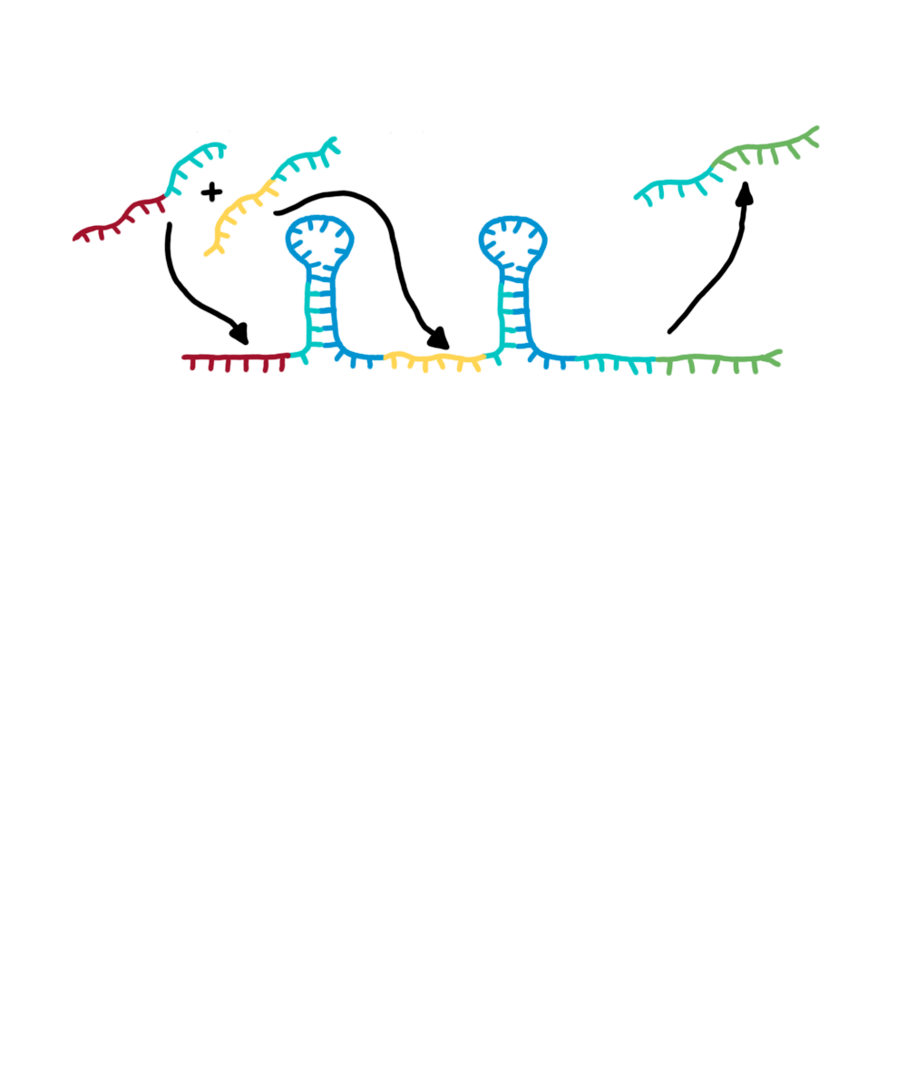
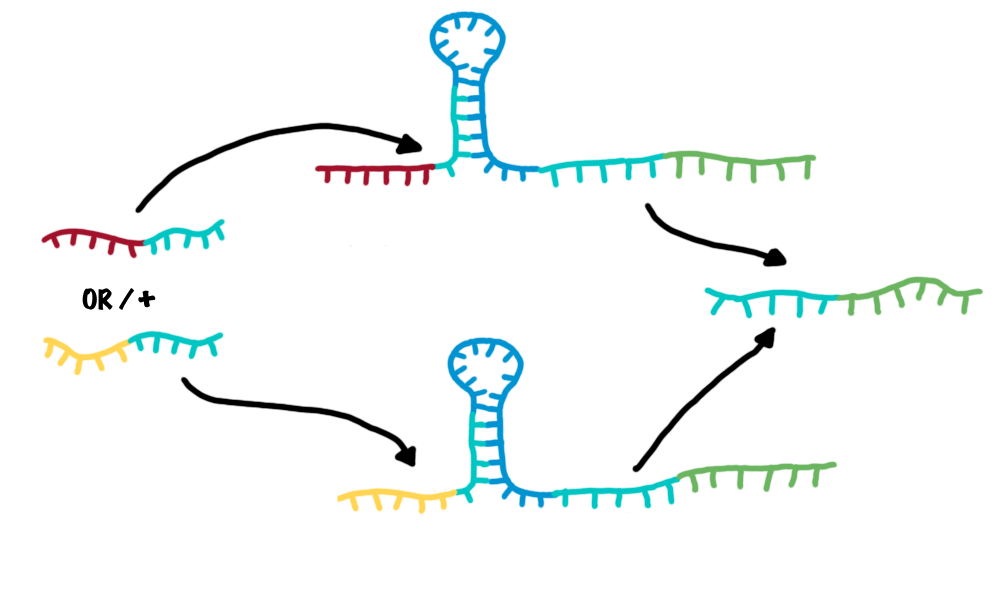
These elements can be combined to build up a molecular network (see illustration). Each input molecule (such as a BioBrick) produces a transmitter molecule that is unique for this input molecule. All transmitters belong to the same type of molecule and share a common design. However each transmitter molecule can only interact and activate a certain subset of logic gates. In other words, logic gates have to recognize and bind the corresponding transmitter molecules. Depending on the type of the logic gate (AND, OR or NOT[6]), an output molecule is only created if both transmitter molecules are present (AND), at least one of two transmitter molecules is present (OR) or if no transmitter is present at all (NOT). Consequently a certain subset of output molecules are generated according to the presence of transmitter molecules, thus also according to the corresponding BioBricks. Computer vs. molecular network
Again, these output molecules are transmitter molecules and can in turn interact with another subset ("layer") of logic gates. In theory many layers of logic gates can be connected by transmitters. The last layer of logic gates has to generate transmitter molecules, that do not interact with logic gates but induce output molecules, such as Biobricks, instead.
Logic gates in a molecular network can be compared to transistors used in a computer where billions of transistors are incorporated. The main advantage on a computer chip is, all transistors share the same functional principle, and only the way of being connected by wires in a special sequence allows specifically adressing only subset of other transistors by an input signal. However, spatial connections are not possible in a living cell. The wiring within a cell relies on the specific interaction between the transmitter molecule and the corresponding logic gates. The main difference is, that each logic unit posses a different xxx . Thanks to evolution, nature easily can invent a new transistor for each task - science achieves this only on a limited scale, and producing synthetic molecular logic gates artificially is limited to small circuits so far. Our project aims to establish a real molecular transistor. Therefore, our smallest switching unit consist of two subunits, a transistor site and a recognition site,which equals Nevertheless, Summarizing, the network established a connection between input BioBrick and output BioBrick in a functional manner.
Design and functional principle of logic gatesThe concept introduced above provides a framework that can potentialy serve as an universal adapter between different BioBricks. However, the logic gates have not been specified more precisely so far. Generally speaking, the logic gates have to posses the following characteristics:
In order to build a logic gates for our bioLOGICS system we will first create a simple toggle switch. A toggle switch can be activated by one RNA and produces an RNA output. In contrast to a logic gate, a toggle switch does not perform logic operations. However by combining two toggle switches, logic gates can be created. The following text will first describe how a toggle switch works and secondly, will demonstrate how logic gates such as AND and OR can be created by combining two toggle switches. Toogle Switch
The switching unit is the functional core element of our switches, allowing a shift between an "on" and "off" state. Since we work on the level of RNA-production (transcription), a "switchable" transcriptional terminator is suitable for this purpose. The principle idea of our switching unit relies on such systems occurring in nature.
It defines the specific access of one of our toogle switches by an input molecule. Therefore, a unique
recognition element is assigned to each switch. This allows to arrange and interconnect numerous
of these switches in a specif logical order, comparable to wires connecting different transistors.
signals, the inputs, transmitters and outputs of the bioLOGICS toggle switchesSignals present the "trigger" to shift switches between the switches´ on and off-state. It requires the ability to change the terminators secondary structure and cause antitermination, BUT only if a special recognition site is detected. Thus, each signal consists of a trigger unit, interacting with the switches´ switching unit and a specifity site, interacting with the terminators recognition site. Practically, the shift between the two terminator states is induced by a complementary RNA-sequence, influencing the terminators secondary structure. But in contrast to previous work [2], we designed this synthetic trigger unit in such a manner it is not able to change the terminator´s state on its own, but only in combination with the specificity site, which is complementary to the recognition site. The challenge is to arrange and optimize these elementary building blocks, that a trigger unit is only able to switch in combination with its respective specificity site. This was done by NUPACK simulations, presented in section in silico design . Putting it all together: the switching processFigure xxx illustrates the functional principle of the designed switch. The switch is implemented in the front a desired output. So in the ground state, transcription will be canceled by the formation of a RNA stem loop in the nascent RNA-chain, which then causes the RNA polymerase to stop transcription and fall off the DNA and no output RNA will be produced.On the other hand, in the presence of a signal, this small functional RNA inhibits the stem loop formation by complementary base-pairing and hence avoids transcription termination. In detail, the specificity unit binds the recognition unit and serves as toehold, which will thermodynamically allow the trigger unit to perform a strand displacement and open the stem loop structure, allowing the polymerase to read through and form the output RNA.
to be competitive to terminator formation - meaning an comparision of kinetic parameters (see Modeling page)
The bioLOGIC toggle switch with regard of logical operationsAs described, each switch can be accessed by a specific RNA-signal molecule, illustrating the input. In turn, another RNA-signal molecule will be produced if the switch shifts its state, now being the output of one switch and at the same time, a possible input for the following switch or several ones. This easily allows arranging several switches in specific sequences and faulty wiring - the corner stone of a logical network. To easen the building of logical networks, applying mathematical logcis, e.g. Boolean logics like in computaltion science would be worthwile. It is possible to establish general Boolean operators with our switches and thus build "logical modules".
Since AND/OR/NOT are the most easy logic operations modularisable with our switches and can substitute all remaining operations, we exemplarly designed them.
Network constructionDesigning complex biological networks based on either traditional protein engineering or our new bioLOGICS is still a complex task. We developed a software which allows the fast construction of a bioLOGICS based networks.
Our ObjectivePutting the implementation described above into pratise, will be a major challenge. For this year's iGEM competition our goal is to do the first step: design and build a switch that can be toggled by a RNA molecule. To be precise, we want to modify a transcription terminator, in such a way, that it interacts with a second RNA molecule and as a result is no longer capable of form a stem loop.
Evaluation and MeasurementsTo evaluate the functionality of our molecular switches, we first had to establish several assays. Therfore, we imporved and tested an existing in vivo assay as well as developed an in vitro assay. For more information please refer to the lab section. ResultsEvery network starts with a basic unit. While our declared aim is to enable networks allowing fine-tuning of gene expression beyond the regular on/off, exploring such an on/off switch/signal pair is the first step towards a functional network. We constructed several units and tested their efficiency, robustness and reproducibility in vivo, in vitro and in silico. Furthermore we developed a software which allows easy constructions of networks delivering a ready network. Conclusive elaboration of a few first RNA-based logic units is the major contribution of our iGEM team. in silico design of switching and trigger unit
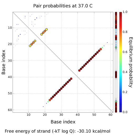
attenuation principleA random sequence was derived from xxx. A complementary sequence, reaching within the terminator´s stem loop was stepwise shortened to find the length, where the formation of the terminator is thermodynamically favored compared to the strand displacement by the signal. The trigger sequence was defined by selecting the shortest unit which still is able to "destroy" the stem loop. Subsequently, the trigger unit was tested in regard of not being able to resolve the stem loop on its on. As table xxx illustrates, the terminator is thermodynamically favorite toward the trigger unit, but in combination with the specificity site, binding becomes possible.
tiny abortive principleubiquitous terminatorsCloseModelingTo read how bioLOGCIS switches theoretically should be able to interrupt termination check out the Modeling page. in vivo functionality screening
in vitro screening
SoftwareTo learn how bioLOGCIS theoretically would allows the construction of complex information processing networks check out the Software page. References[1] http://partsregistry.org/cgi/partsdb/Statistics.cgi [2] https://2009.igem.org/Team:Imperial_College_London/M1 encapsulation [3] https://2009.igem.org/Team:TUDelft [4] https://2008.igem.org/Team:Heidelberg [5] Smolke and so on.... [6] http://en.wikipedia.org/wiki/Logic_gate#Symbols [7] [8] [9] [10] [11] [12] [13] [14] [15] [16]
|
|||||||||||||
 "
"


