Team:Brown/Project/Light pattern/Results modeling/Modeling
From 2010.igem.org
| (6 intermediate revisions not shown) | |||
| Line 3: | Line 3: | ||
{{:Team:Brown/templates/Lpmenu}} | {{:Team:Brown/templates/Lpmenu}} | ||
==Results and Modeling== | ==Results and Modeling== | ||
| - | + | Although we have not yet been able to characterize physical parts for our circuit, the in-silico analyses detailed on our [[:Team:Brown/Modeling/Results|Modeling Results]] page indicate that our circuit will function. | |
| - | + | [[Image:Four.jpg|600px]] | |
| - | + | ||
| - | + | ||
| - | + | As opposed to our original prediction that the circuit would cycle through the following progression, | |
| - | + | S1 -> S2 -> S2+S3 -> S2+S4 -> S1 -> S2 -> S2+S3 -> S2+S4 -> S1... | |
| - | + | ||
| - | + | ||
| - | + | We now see that the circuit will cycle through states as follows: | |
| - | + | ||
| - | + | ||
| - | + | ||
| - | + | ||
| - | + | S1 -> S2 -> S2+S3 -> S2+S4 -> S2+S3 -> S2+S4 -> S2+S3... | |
| - | + | ||
| - | + | Instead of resetting after S4 is expressed, the circuit cycles between State 3 and State 4. Additionally, we see a small peak of S3 at the beginning of the cycle from a cell at base state. We predict that in a living system this will not be as pronounced as in the model. We suggest solutions for both of these issues on the [[:Team:Brown/Modeling/Results|Modeling Results]] page. | |
| - | + | ||
| + | By the time we attend the Jamboree, we hope to have completed the [[:Team:Brown/Project/Light_pattern/Logic_design#Conversion_Module|Conversion Module]] with CI and a terminator, such that it will be able to activate the bistable switch part from PKU. Since both parts have fluorescent reporters already integrated, visualization of expression should be a simple matter. Successfully integrating these two parts into a light-activated bi-stable system is an important step towards the completed quad-state circuit. | ||
Latest revision as of 23:57, 27 October 2010
Light-Pattern Controlled Circuit
Results and Modeling
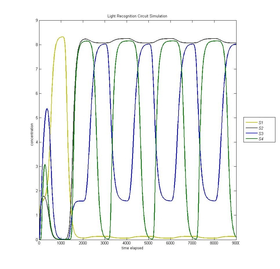
Although we have not yet been able to characterize physical parts for our circuit, the in-silico analyses detailed on our Modeling Results page indicate that our circuit will function.
As opposed to our original prediction that the circuit would cycle through the following progression,
S1 -> S2 -> S2+S3 -> S2+S4 -> S1 -> S2 -> S2+S3 -> S2+S4 -> S1...
We now see that the circuit will cycle through states as follows:
S1 -> S2 -> S2+S3 -> S2+S4 -> S2+S3 -> S2+S4 -> S2+S3...
Instead of resetting after S4 is expressed, the circuit cycles between State 3 and State 4. Additionally, we see a small peak of S3 at the beginning of the cycle from a cell at base state. We predict that in a living system this will not be as pronounced as in the model. We suggest solutions for both of these issues on the Modeling Results page.
By the time we attend the Jamboree, we hope to have completed the Conversion Module with CI and a terminator, such that it will be able to activate the bistable switch part from PKU. Since both parts have fluorescent reporters already integrated, visualization of expression should be a simple matter. Successfully integrating these two parts into a light-activated bi-stable system is an important step towards the completed quad-state circuit.
 "
"
