Team:TU Munich/Software
From 2010.igem.org
Hartlmueller (Talk | contribs) (→Examples) |
Hartlmueller (Talk | contribs) (→1. Construct a logic network) |
||
| Line 40: | Line 40: | ||
==1. Construct a logic network== | ==1. Construct a logic network== | ||
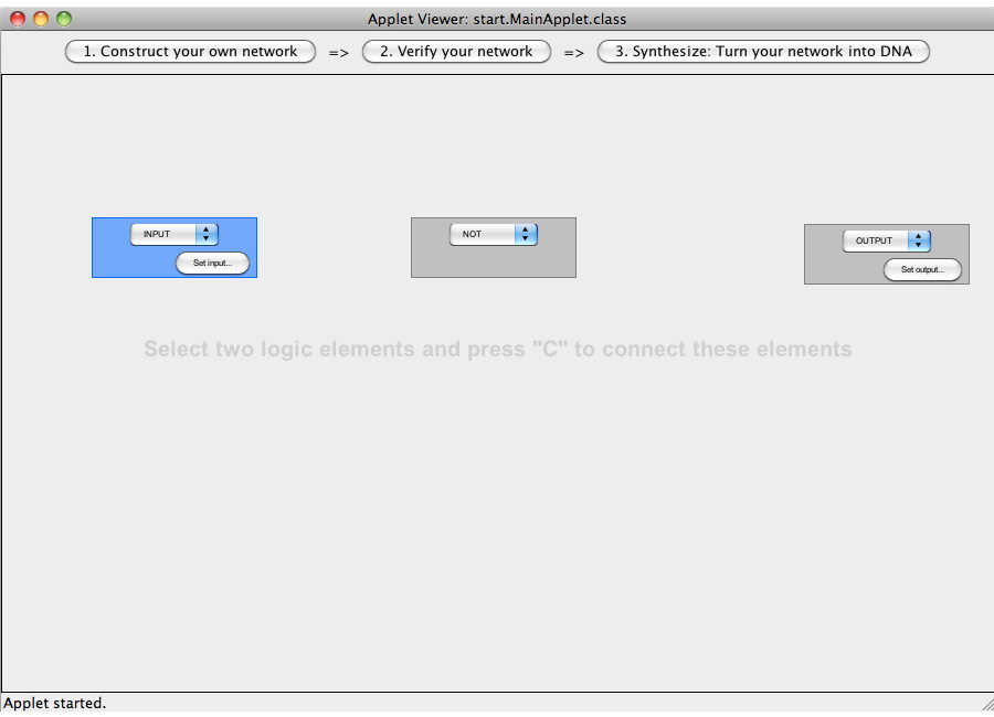
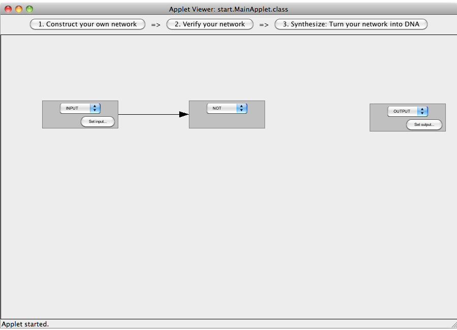
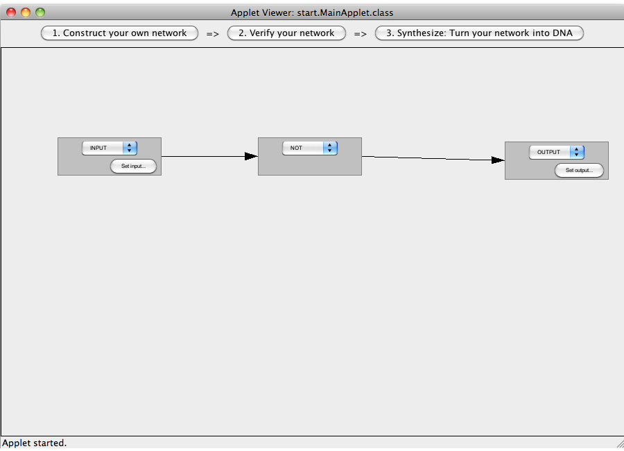
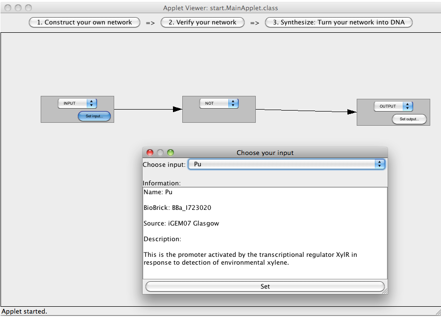
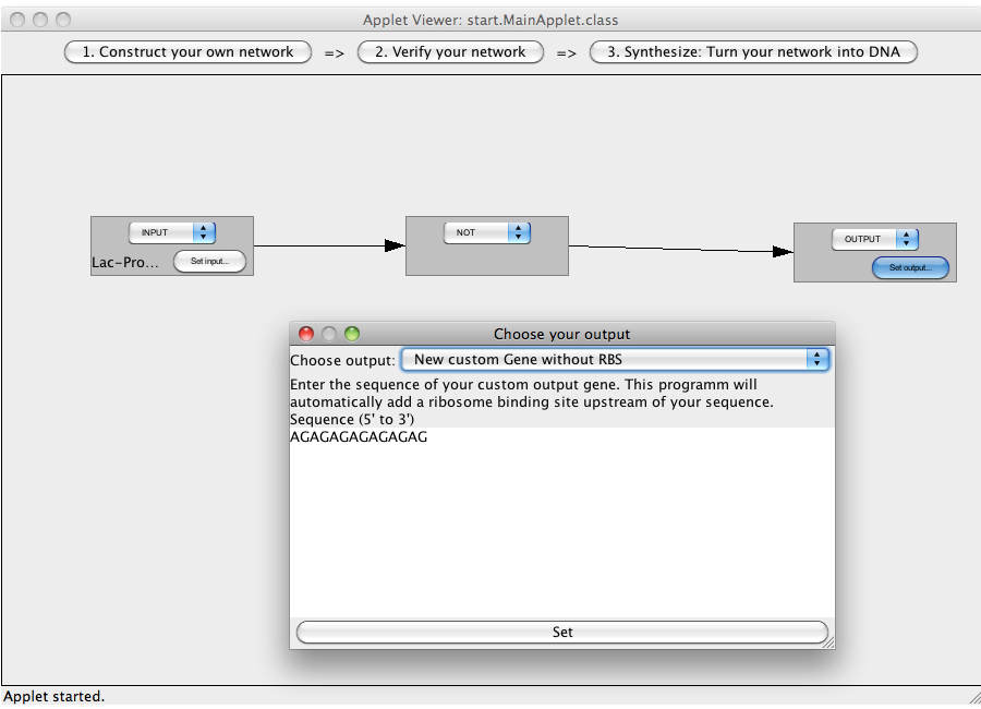
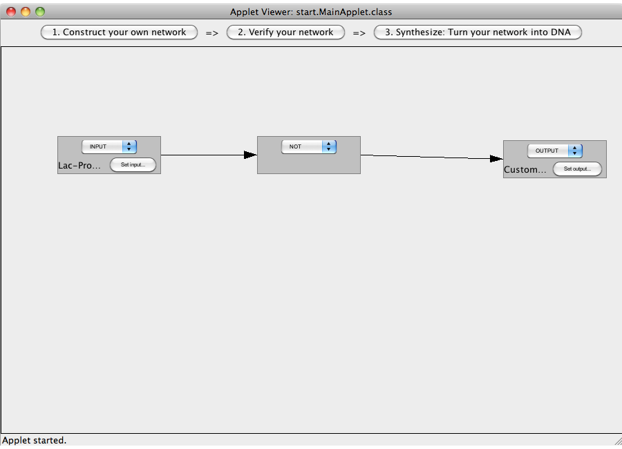
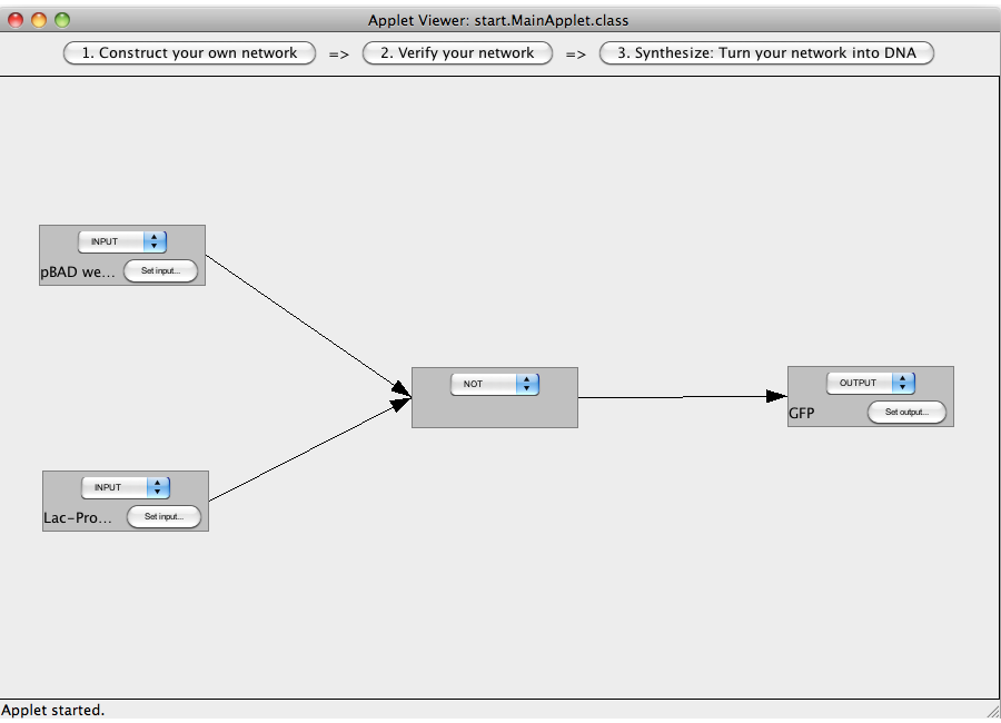
| + | The following "Read more" section will provide step-by-step instructions for creating a simple network, connecting two Biobricks with a NOT gate. | ||
{{:Team:TU Munich/Templates/ToggleBoxStart}} | {{:Team:TU Munich/Templates/ToggleBoxStart}} | ||
A '''logic network''' can be designed by adding logical devices (via double clicking) and interconnecting them. | A '''logic network''' can be designed by adding logical devices (via double clicking) and interconnecting them. | ||
Revision as of 15:40, 24 October 2010
|
||||||||
|
|
MotivationAs described in the project section, our vision is to provide a system that allows to connect various BioBricks. It is further descirbed that such a system requires logic gates that can be interconnected. The major goal of this project and future work is to optimize the design of these switches.
ProgramClick here to start the program (loading may take a few seconds during which an empty wiki page is displayed). If you use the software for the first time, you might want to take a look at the tutorial or the step-by-step examples on how to use the program. Please feel free to download the source code of this program. To find more information about the Biobricks used within the program, see the following "Read more" section. The plasmid generated by the program is based on the [http://partsregistry.org/Part:pSB1A3 pSB1A3 backbone] which is a frequently-used plasmid carrying an ampicilin resistance. The design used for the logic gates is based on the His-Terminator design (see project for details). If required for output proteins the ribosome binding site [http://partsregistry.org/Part:BBa_B0034 B0034] was used. For the constitutive promoter, positioned upstream of every logic gate, the software uses the [http://partsregistry.org/Part:BBa_J23100 J23100] promoter. Details about input and output Biobricks are supplied within the program. CloseTutorialThe program consists of three modules: Construct, Verify and Synthesize. The first allows the user to enter inputs, whereas the second and third supply the user with information about his network.
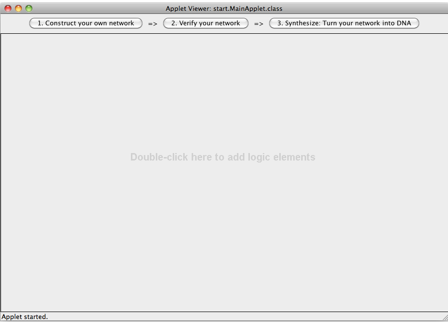
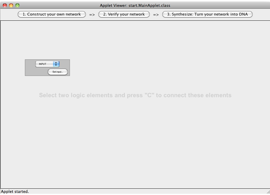
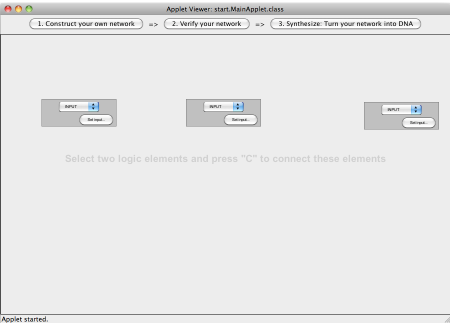
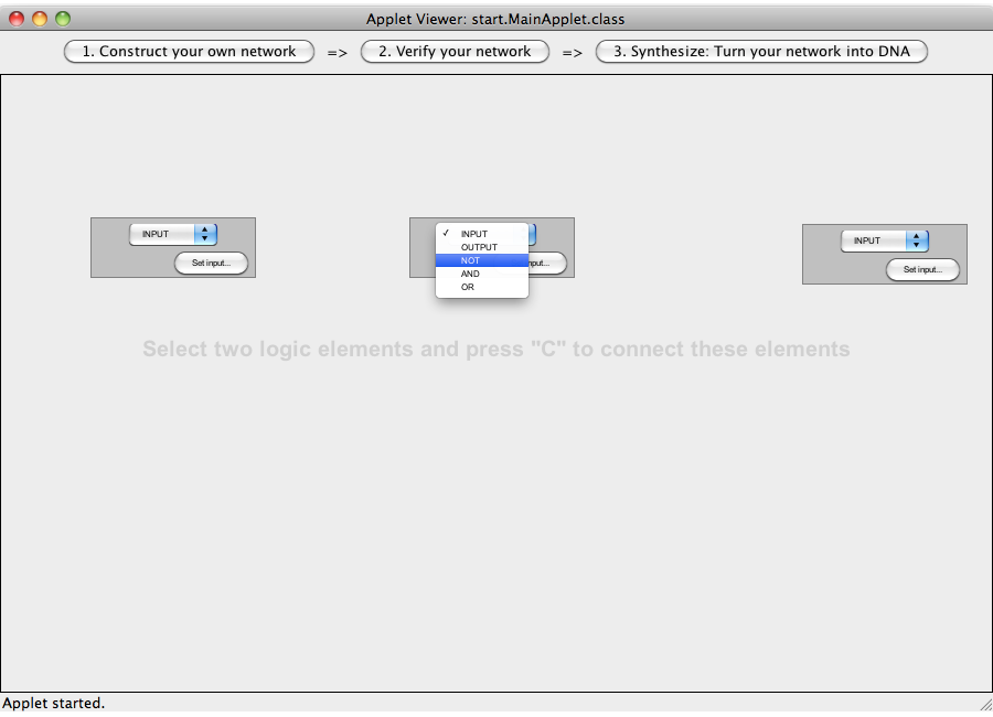
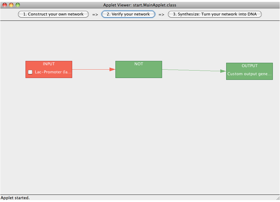
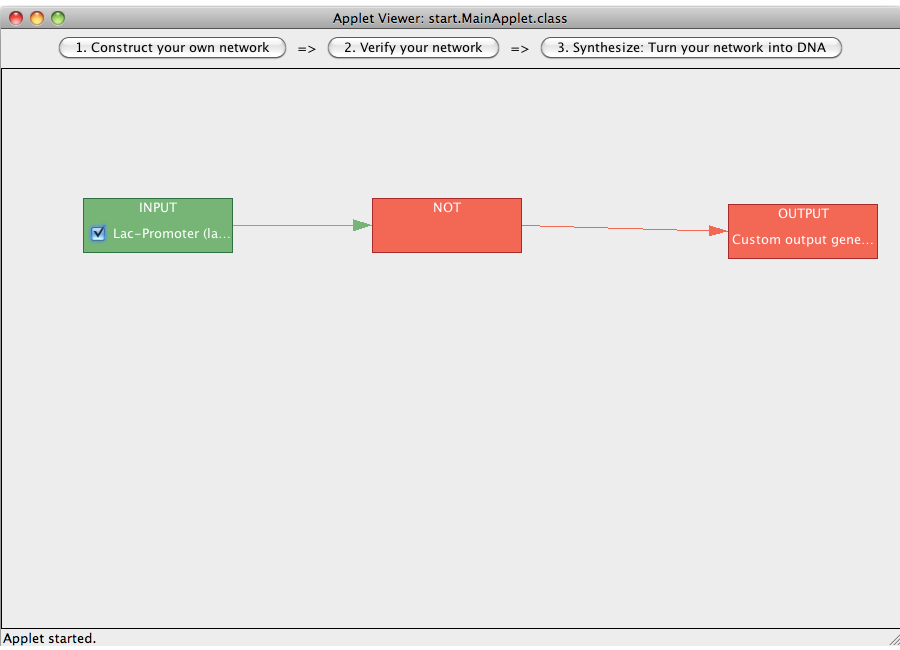
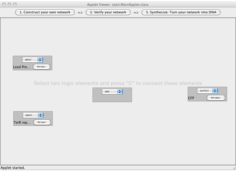
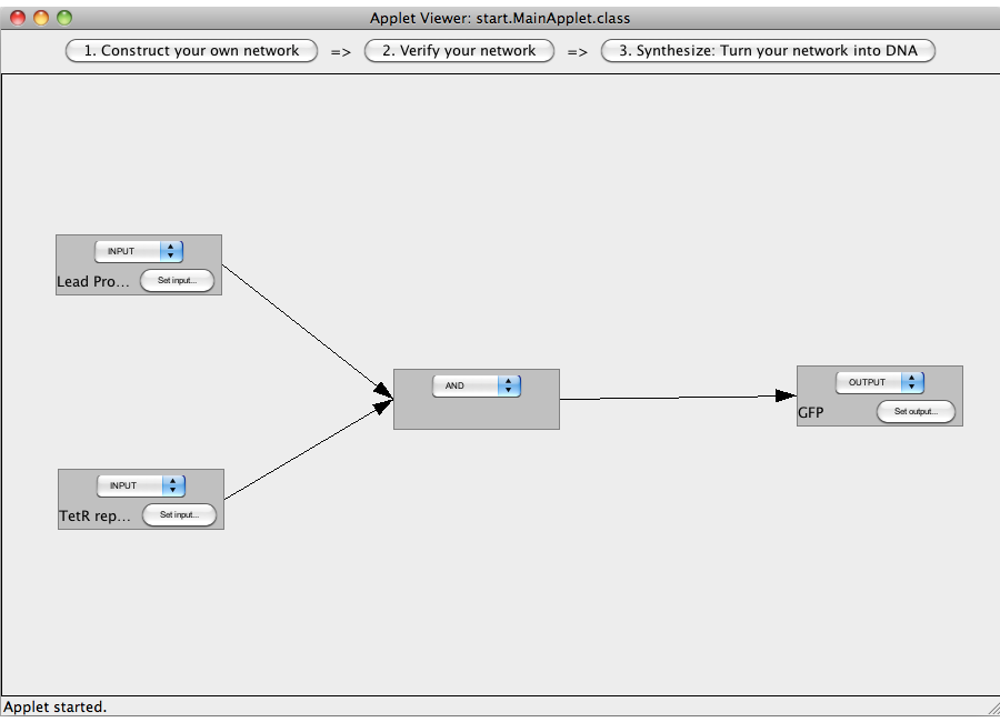
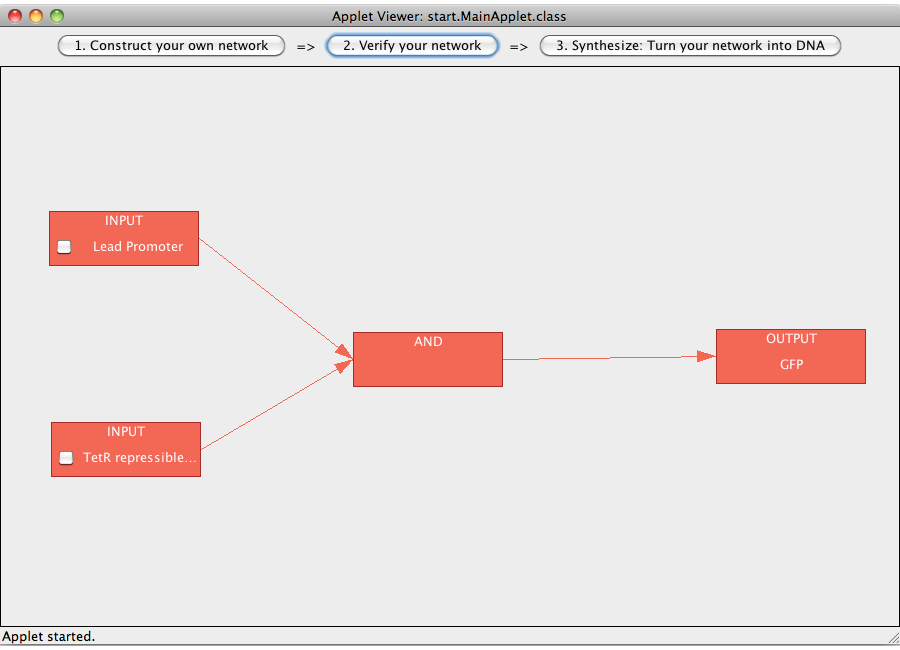
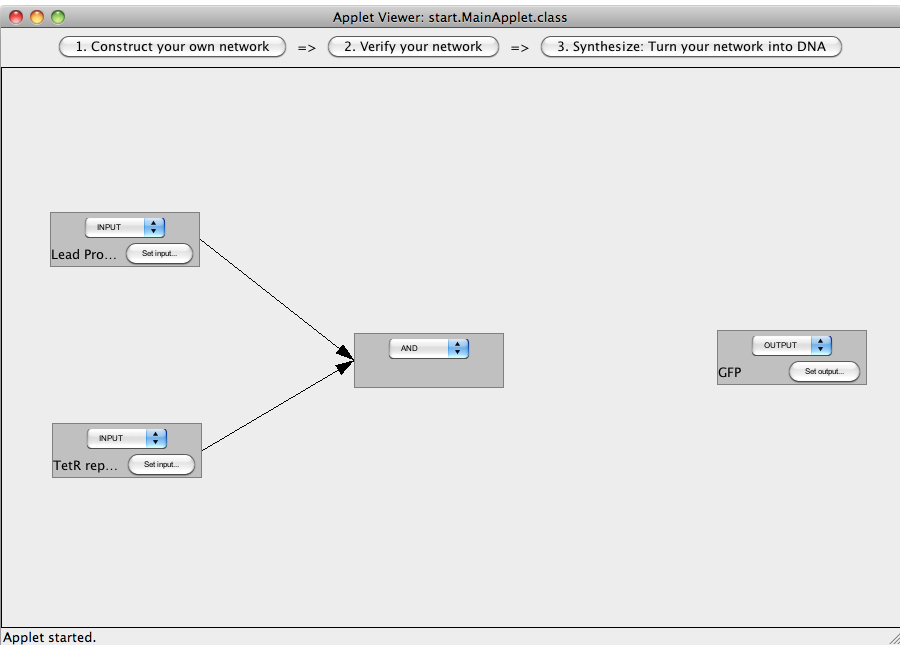
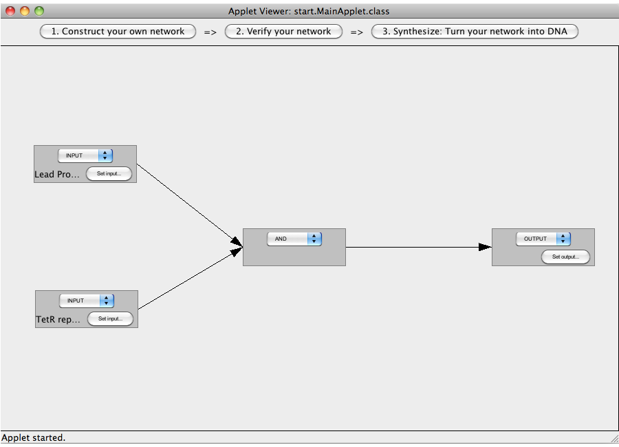
Verify: This module illustrates in the colors green for true and red for false which nods and relations are assigned the values 'true' or 'false'. Sythesize: This module assigns the abstract logic network concrete sequences, e.g. terminator sequences, generates random sequences and provides all the genetic information to rebuild the network. The different modules are described in detail below. 1. Construct a logic networkThe following "Read more" section will provide step-by-step instructions for creating a simple network, connecting two Biobricks with a NOT gate. A logic network can be designed by adding logical devices (via double clicking) and interconnecting them. There are five different types of logical devices: inputs, outputs, AND-gates, OR-gates and NOT-gates. The type of a local device can be change by clicking on the combo box on the device and selecting a different type. Logical devices can be interconnected by selecting (via clicking inside the area of a device) two devices and then pressing the C key (for connect). A complete logic network has to have at least one input, at least one output, and at least one gate (AND, OR, NOT). Different devices may require different numbers of ingoing and outgoing connections (e.g. a NOT-gate requires one ingoing connection and allows for an arbitrary number of outgoing connections, whereas the AND-gate requires two ingoing connections and allows for a arbitrary number of outgoing connections; an input may not have an incoming connection, an output no outgoing connection). In addition the logic network may not include loops. The user has to assign DNA sequences (either custom RNA sequences or sequences coding for proteins) to all input and output devices by clicking on the "Set input" button of the devices.
2. Verify the logic network
The logic network designed in step 1 can now be verified. Logical values are represented by colors (green = true, red = false). Thus a green box represents a devices (e.g. an AND-gate) with the logical value true, a red box a devices with the logical value false. The flow of logical value can be followed by following the colored edges between the boxes. The logical value(s) of the input(s) can be manipulated by clicking on their checkbox(es). Close
3. Synthesize - Turn the logic network into DNA
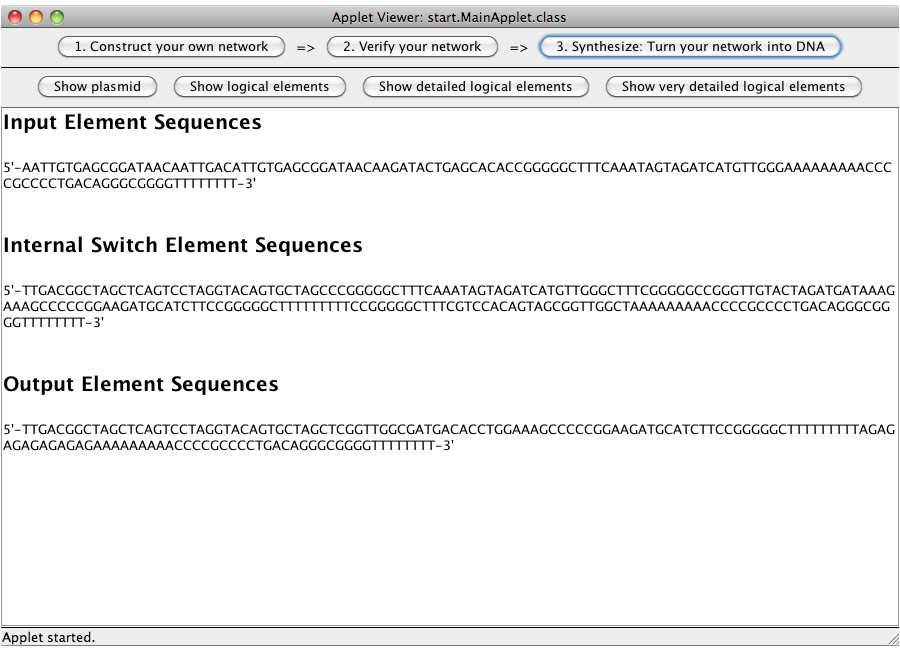
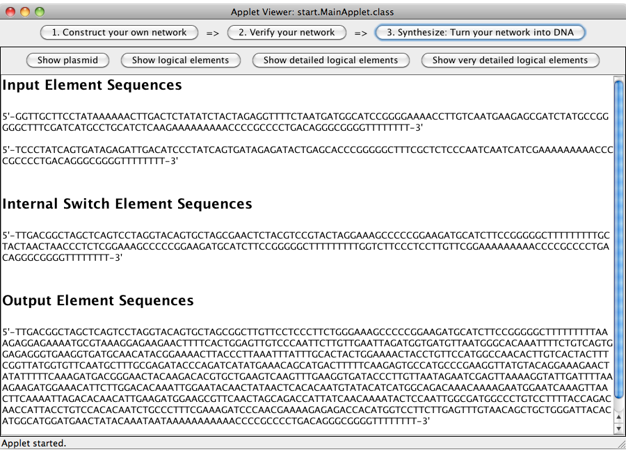
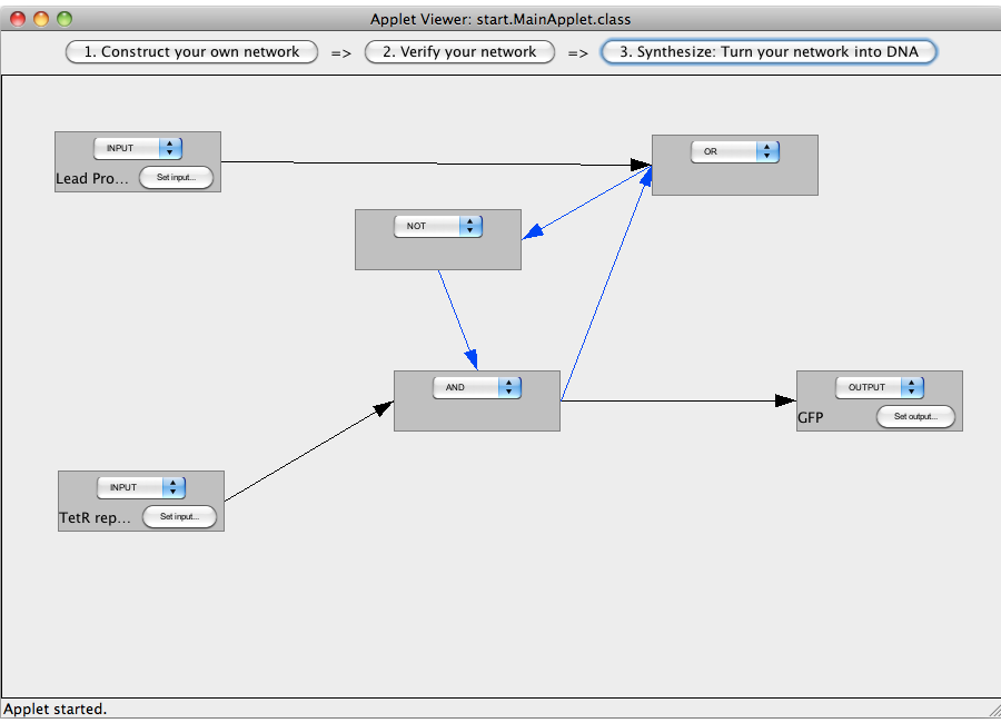
A set of genetic devices (categorized as input elements, switch elements and output elements) representing the logical network designed in step 1 is calculated and displayed. All elements consist of a promoter, a ribosome binding site, up to two switches, one output sequences and a terminator. CloseExamplesA NOT-gate (introductory)
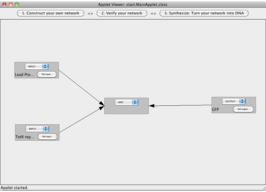
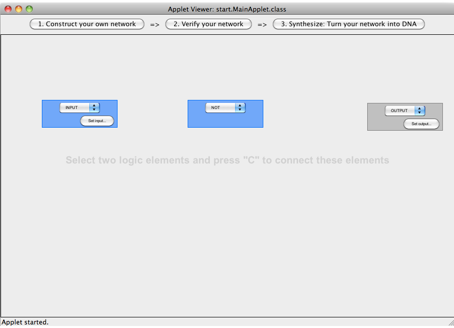 Step 07: To connect two logical devices select both. Note that the connections has a direction (which will be indicated by an arrow), thus you have to select the logical devices in the correct order: first, select the box from which the connection starts and then select the box where the connection ends (The arrow points from the box that generates an output molecule, to the target box that will be activated by this output). You can only connect logical devices pairwise. Close An AND-gate
Common mistakes
DisclaimerSoftwareTHIS SOFTWARE IS PROVIDED BY THE CONTRIBUTORS "AS IS" AND
ANY EXPRESS OR IMPLIED WARRANTIES, INCLUDING, BUT NOT LIMITED TO, THE IMPLIED
WARRANTIES OF MERCHANTABILITY AND FITNESS FOR A PARTICULAR PURPOSE ARE
DISCLAIMED. IN NO EVENT SHALL THE CONTRIBUTORS BE LIABLE FOR ANY
DIRECT, INDIRECT, INCIDENTAL, SPECIAL, EXEMPLARY, OR CONSEQUENTIAL DAMAGES
(INCLUDING, BUT NOT LIMITED TO, PROCUREMENT OF SUBSTITUTE GOODS OR SERVICES;
LOSS OF USE, DATA, OR PROFITS; OR BUSINESS INTERRUPTION) HOWEVER CAUSED AND
ON ANY THEORY OF LIABILITY, WHETHER IN CONTRACT, STRICT LIABILITY, OR TORT
(INCLUDING NEGLIGENCE OR OTHERWISE) ARISING IN ANY WAY OUT OF THE USE OF THIS
SOFTWARE, EVEN IF ADVISED OF THE POSSIBILITY OF SUCH DAMAGE.
BiologyTHIS SOFTWARE IS FOR DEMONSTRATION PURPOSES ONLY. THE WARRANTY OF FITNESS FOR A PARTICULAR PURPOSE, INCLUDING THE DESIGN OF FUNCTIONAL GENE CIRCUITS, IS DISCLAIMED. ESPECIALLY DO NOT USE THE SOFTWARE IN THE PROCESS OF DESIGNING REAL EXPERIMENTS OR ORDERING GENETIC DEVICES / SEQUENCES.
|
|||||||
 "
"


