Team:TU Munich/Modeling
From 2010.igem.org
|
||||||||||||||||||||||||||||||||||||||||||||||||||||||||||||||||||||||||||||||||||||||||||||||||||||||
|
|
OverviewIn the modeling part of our project we investigated the static (in silicio design) and the dynamical (diffusion and RNA Folding Dynamics) properties of our signal-terminator constructs (switch).
ResultsTODO: kurze Zusammenfassung der Resultate des in silicio designs von Tilli
in silico design based on thermodynamic calculationsIn the following section we will describe how we theoretically designed our switches and their respective transmitter molecules. Our goal was to develop synthetic modified terminators consisting of a target and recognition site in the described manner(compare Implementation. As explained, only the complete transmitter RNA may shift the switches´ state and not the trigger site nor the identity site on their own. This is the prerequisite to fulfill all mentioned requirements for a functional switch allowing to construct logical gates as discussed previously. We implemented this by optimizing the thermodynamically parameters for pairing of each subsegment (identity site, trigger site, recognition site, target site).
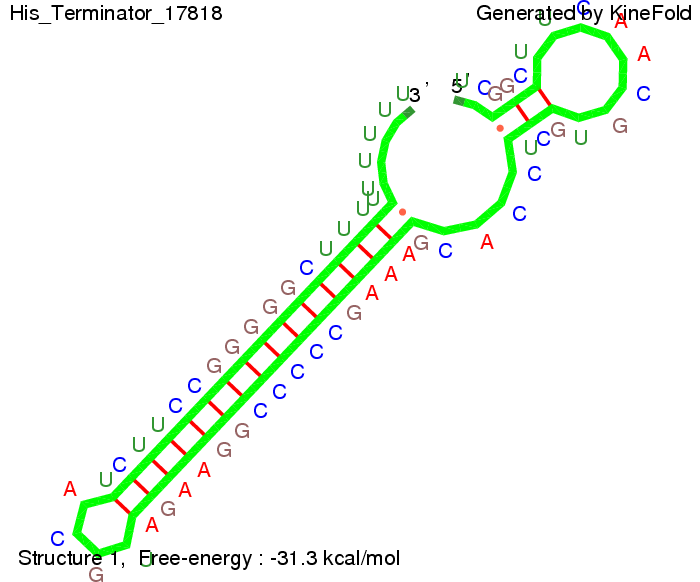
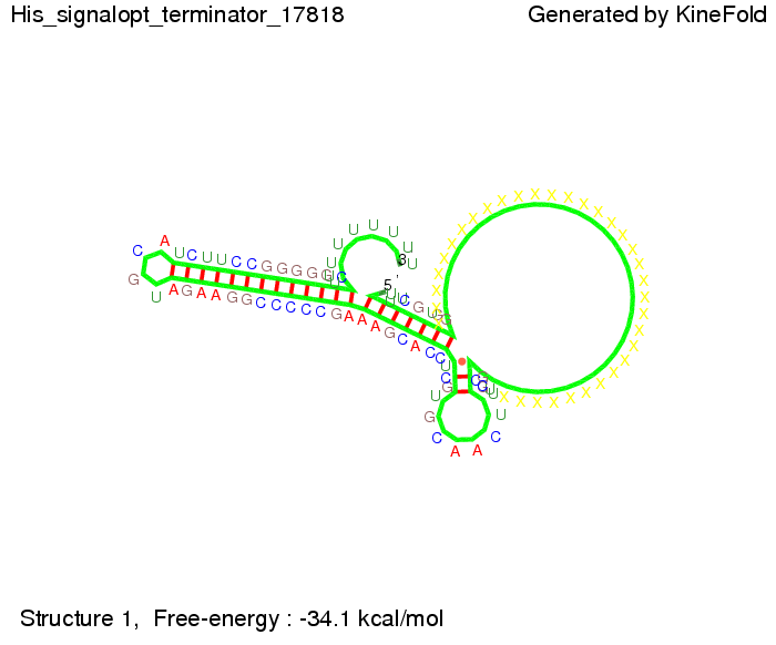
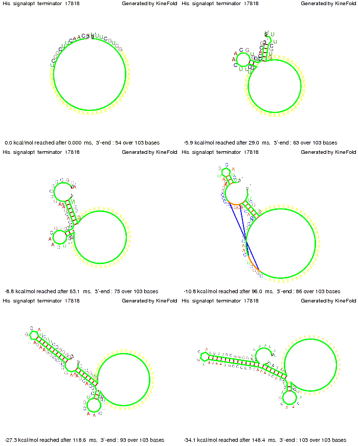
attenuation principleOn a first approach, we designed switches based on terminators performing antitermination in the context of their natural occurrence within the scope of attenuation, the His and Trp terminator.[1][2]. A 20 bp random sequence was derived from random sequence generator and put upstream the terminator loop. A complementary sequence, reaching within the terminator´s stem loop (the transmitter) was stepwise shortened to find the length, where the formation of the terminator is thermodynamically favored compared to the strand displacement by this sequence. The final transmitter sequence was then defined by selecting this shortest strand which is still able to "destroy" the stem loop. Subsequently, the complementary random sequence (identity site) was removed an the remaining trigger site was tested in regard of not being able to resolve the stem loop on its on. As illustrated for the His-based switch below, the terminator is thermodynamically favored toward the trigger unit, but in combination with the identity site, destroying the terminator´s stem loop becomes possible.
br>
ubiquitous terminators
tiny abortive principleCloseDiffusionThe question whether antitermination occurs is not only guided by the folding process of the signal-terminator pair, but also by how long the signal takes to diffuse to the terminator sequence.
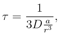
To account for the diffusion time, we estimated the hit rate τ[2], which is the time until the signal meets the terminator sequence for the first time:
where D is the diffusion constant, a the radius of gyration of the signal molecule and r the radius of the compartment.
where n is the length of the signal which is 0,3 nm/monomer, l is the persistency length[4] which is 2nm for single-stranded RNA. Thus, for a signal of length 32 nt, a = 6,4 nm. The diffusion constant D was obtained by
where kB is the Boltzmann constant and T is the absolute temperature. Thus, for a cell containing 100 signal molecules, the signal needs approximately 0,1518 sec until it first hits the terminator sequence. CloseResultsAs the folding time (at least 1,7 sec for full signal length) is significantly larger than the estimated diffusion time (0,1518 sec), diffusion does not play an important role and thus can be neglected in the modeling our signal-terminator constructs. SwitchTo understand the RNA-folding dynamics of our switch including switching process, we performed Kinefold simulations for the His-terminator, the Trp-terminator and for the T7-terminator, each with the corresponding signal. For each terminator-signal construct, there are folding path videos available below and we optimized the signal sequences.
I. His-terminatorTerminator sequence: Both terminator and signal sequence comprise two parts:
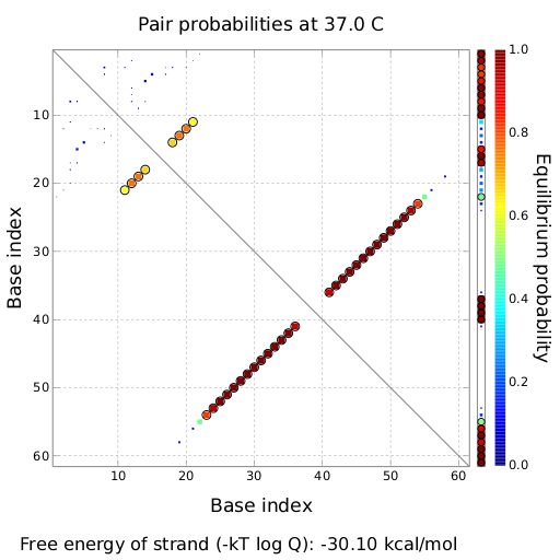
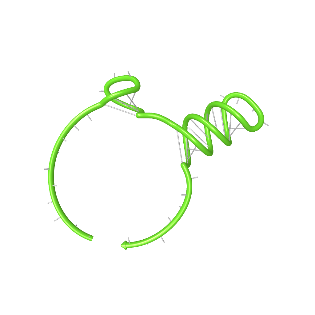
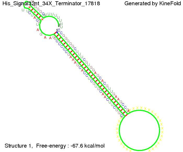
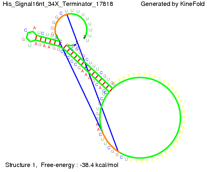
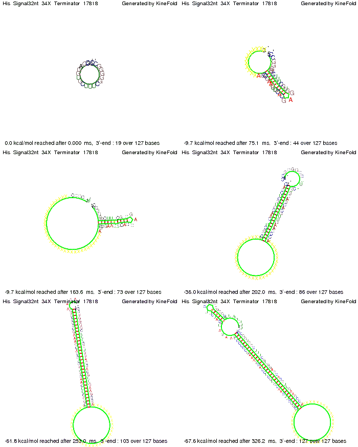
We modeled the signal-terminator interaction for 2, 4-32 nt signal length and find that the signal sequence binds to the terminator sequence and impedes the terminator folding, thus the polymerase doesn't fall off and the output signal can be produced. The minimal free-energy structure of the folded terminator including the random signaling part is shown in the figure "His-terminator" below: Our full signal sequence of length 32 nt completly binds to the terminator leading to antitermination. On the other hand the picture for a signal length of only 2 nt shows that such a small signal length is not sufficient to induce antitermination. But already a signal of length 16 nt binds to the terminator so that it cannot fold completely anymore leading to antitermination. Furthermore, we explored whether the artificial linker has any influence on the results.
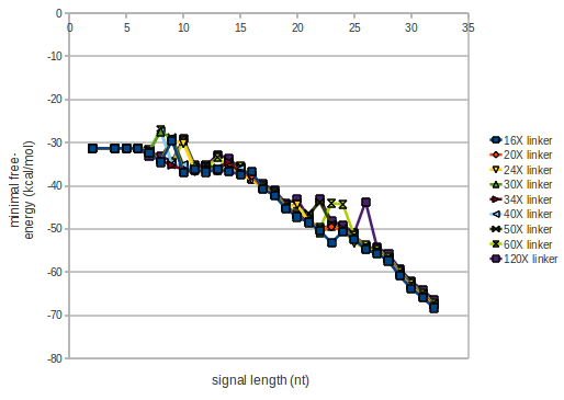
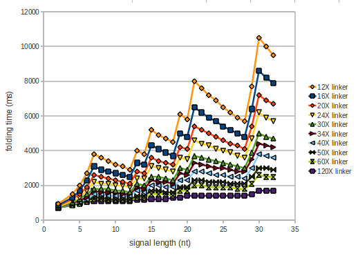
As we observed a dependence of the folding time and minimal energy respectively from the linker length we used linkers of length 12, 16, 20, 24, 30, 34, 40, 50, 60, 120 'X' bases.
For the minimal energy there is only a very small linker length dependence as one can see in the figure below.
However, for the folding time the linker length dependence is significant as one can see in the figure below. But, as, for us, the fact whether the terminator is folding or not is crucial and the videos below show that for appropriate signal length the terminator is not folding. Concerning this fact, for all linker lengths we tested there was only a dependence on the signal length but the results were independent from the linker length. Hence, the linker length dependence and thus the linker itself can be neglected since it only affects the folding process quantitatively but not qualitatively.
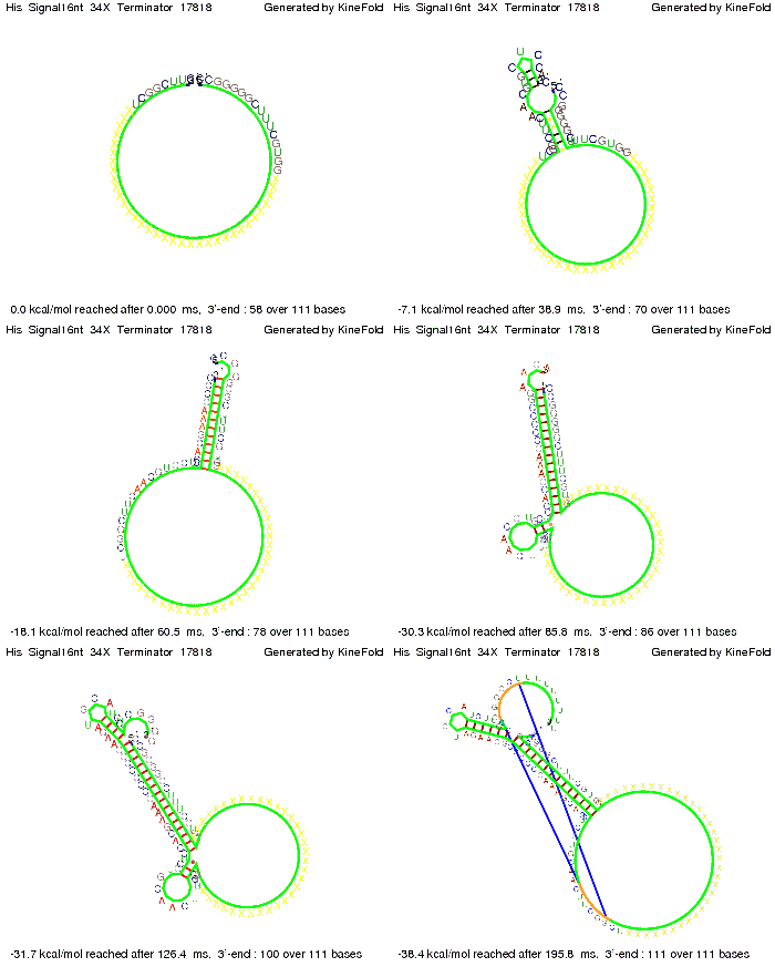
RNA folding path videosThe video on the left for 16 nt signal length shows that the terminator is already hindered from folding completely and the video on the right, which is done for full signal length of 32 nt, displays that the terminator does not fold at all as the signal immediately binds to the terminator sequence as it is synthesized.
Finally we optimized the signal sequence and obtained a signal sequence of only 8 nt length.
Optimization of the signal sequenceWe also tried to optimize our signal sequence to find the minimal sequence length which still enables antitermination. For this optimization kept the random signaling part constant and varied the part which partially binds to the His-terminator and vice versa to see which length is sufficient for antitermination for each case. Then we combined the results to find a optimal signal.
When varying the part which partially binds to the His-terminator we found that having only the 2 nt of this part together with the random signaling part suffices for antitermination as the picture and the corresponding video below show.
For the full 12 nt of the part which partially binds to the His-terminator, the random signaling part has to have at least 2 nt in order to prevent termination as one can see in the picture below.
We then combined these two results: Above one always had the full length of either one of the two parts of the signal, as we now wanted to modify both parts and only 2 nt of each part were not sufficient for antitermination, we finally discovered that a signal with overall 8 nt, 4 nt for the random signaling part and 4 nt for the part which partially binds to the His-terminator, 5' UUUCGUGG 3', suffices to enable antitermination as the picture and the corresponding video below display.
Close Close Close ResultsWe showed that in theoretical simulations the His-terminator works perfectly as the terminator itself is relatively stable whereas for appropriate signal length the terminator is not folding at all, that is antitermination occurs. We also demonstrated that a quite short signal length of 8 nt is sufficient for antitermination to happen. Nevertheless longer signals providing a larger 'namespace' can also be used, 8 nt is only the minimal length for our switch to function. II. Trp-terminatorTerminator sequence: Both terminator and signal sequence comprise two parts:
We modeled the Trp-terminator-signal interaction, generated folding path videos that give more insight in its dynamics and optimized the signal sequence.
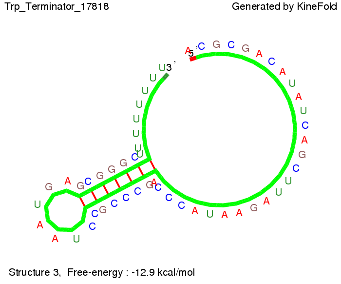
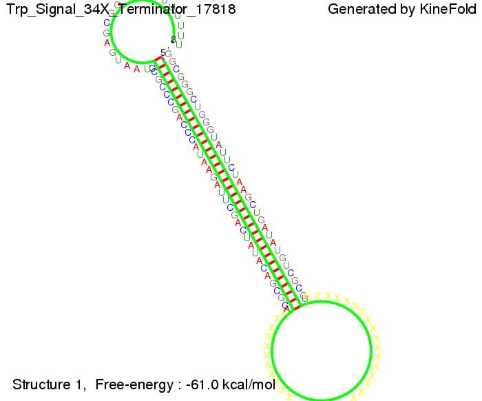
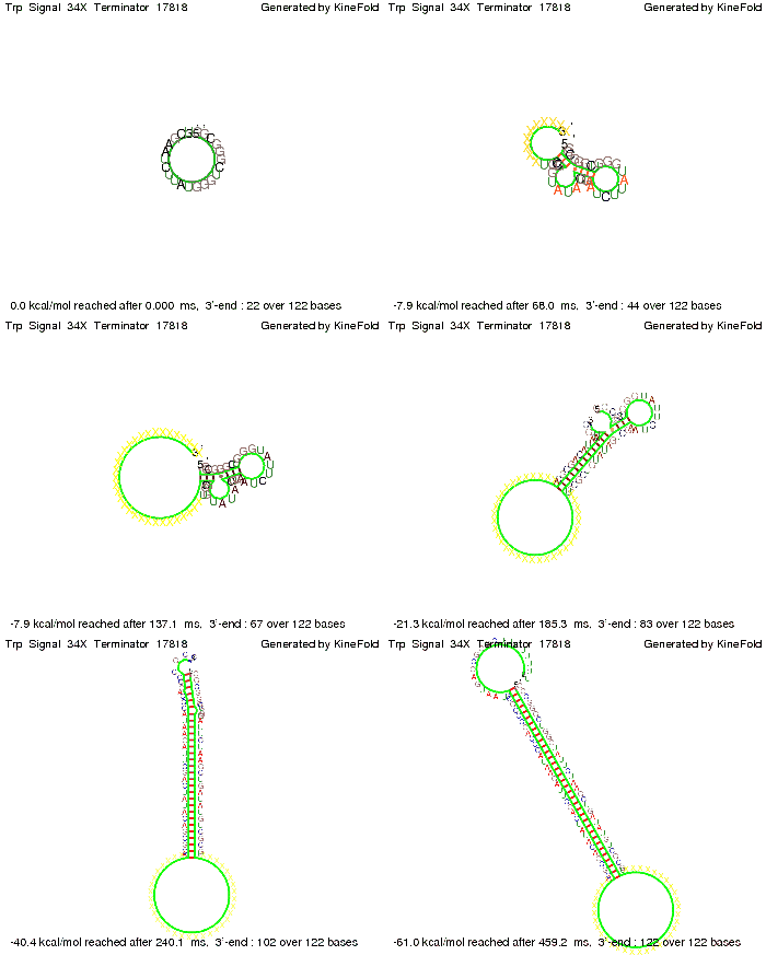
The Trp-terminator turned out to be less stable than the His-terminator. The folded terminator is not the minimal free-energy structure for the given the RNA sequence, it's only the third minimal one at -12.9 kcal/mol compared with the His-terminator which has a minimal free-energy structure at -31.3 kcal/mol. The folded terminator including the natural sequence part upstream of the Trp-terminator binding to the terminator in antitermination state and the random signaling part is shown in the figure "Trp-terminator" below: Our full signal sequence of length 34 nt completly binds to the terminator and antitermination is successful:
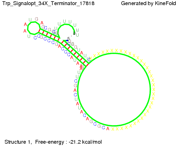
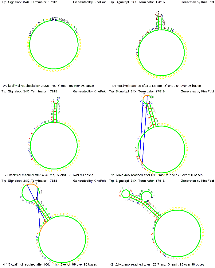
Optimization of the signal sequenceAs for the His-terminator, we tried to optimize our signal sequence to find the minimal sequence length which still enables antitermination. It turned out that a signal with overall 10 nt, 2 nt for the random signaling part, all 6 nt for the part which binds to the upstream sequence of the terminator and 2 nt for the part which partially bind to the Trp-terminator, 5' CUGGGUAUUC 3', suffice to enable antitermination as the picture and the corresponding video below display.
ResultsWe showed that the Trp-terminator should function properly. Although the terminator itself is less stable than the His-terminator for appropriate signal length the terminator is not folding, thus antitermination occurs. We also demonstrated that a signal length of 10 nt is sufficient for successful antitermination. III. T7-terminatorTerminator sequence: Both terminator and signal sequence comprise two parts:
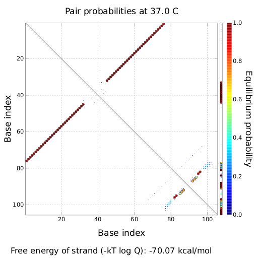
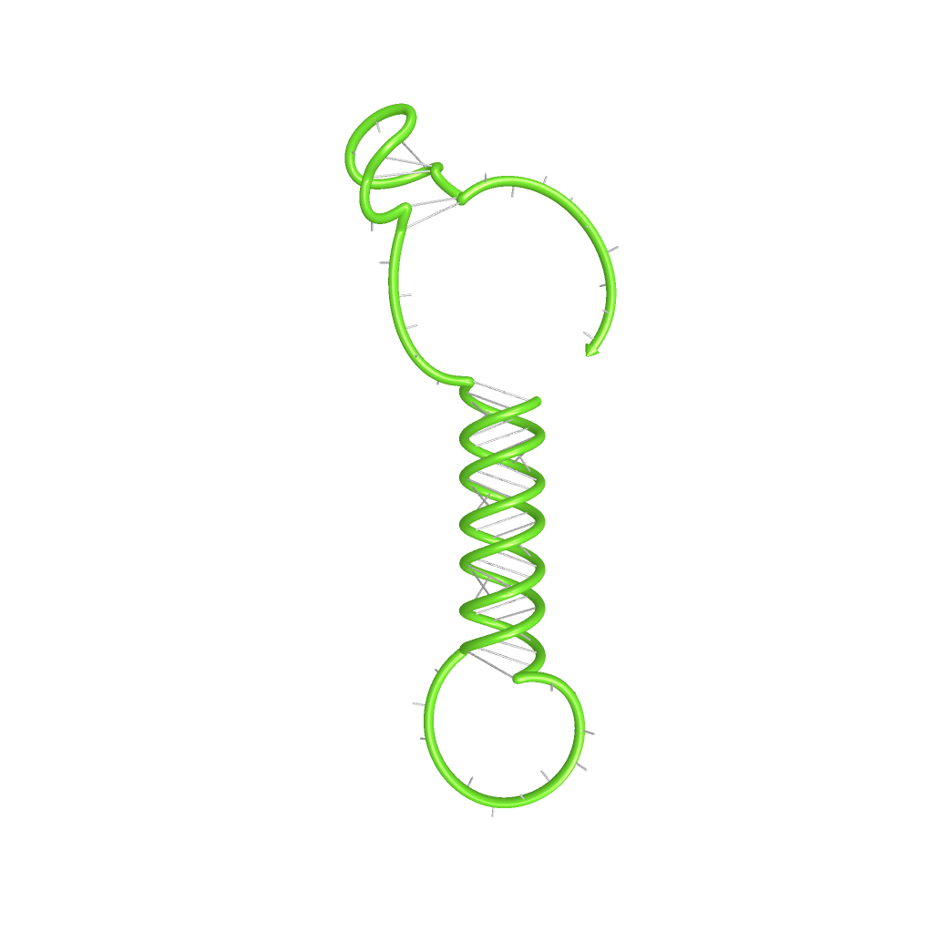
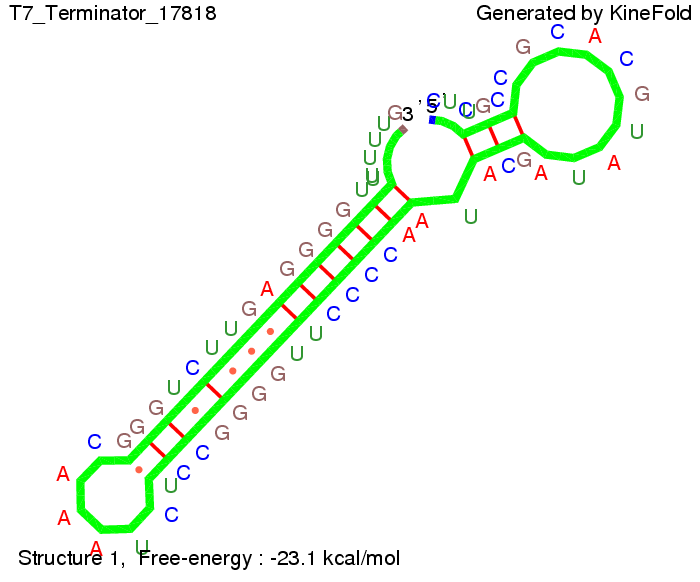
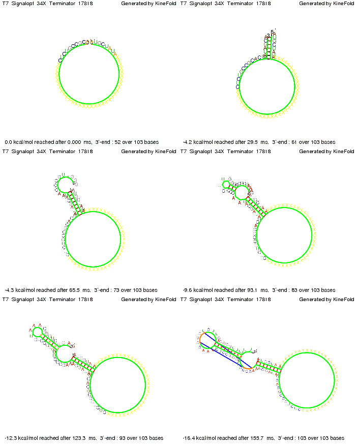
We also modeled the T7-terminator which is also less stable than the His-terminator. Its minimal free-energy structure is at -23.1 kcal/mol. The folded terminator including the random signaling part is shown in the figure "T7-terminator" below: Our full signal sequence of length 28 nt completly binds to the terminator and anti-termination is successful:
Optimization of the signal sequenceAs for the His-terminator, we tried to optimize our signal sequence to find the minimal sequence length which still enables antitermination. We finaly found that a signal with overall 8 nt, 3 nt for the random signaling part and 5 nt for the part which partially bind to the T7-terminator, 5' AUGCUAUA 3', suffice to enable anti-termination as the picture and the corresponding video below display.
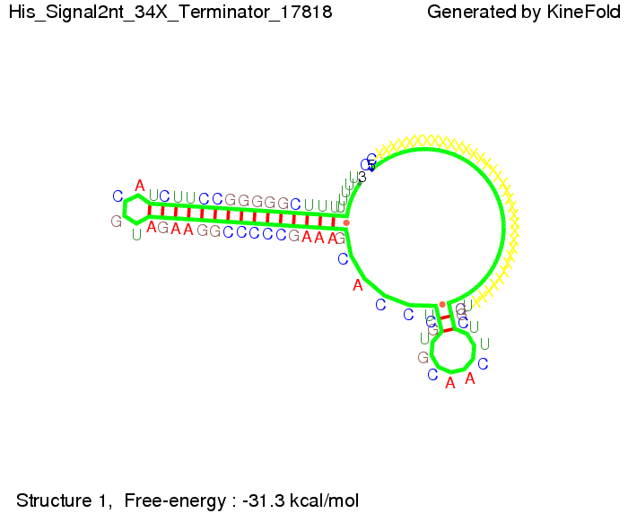
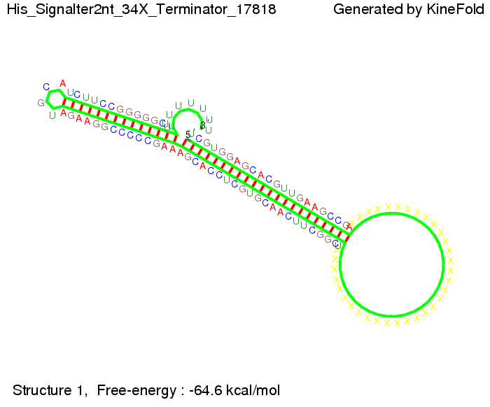
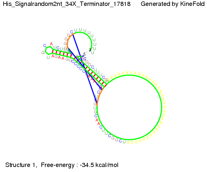
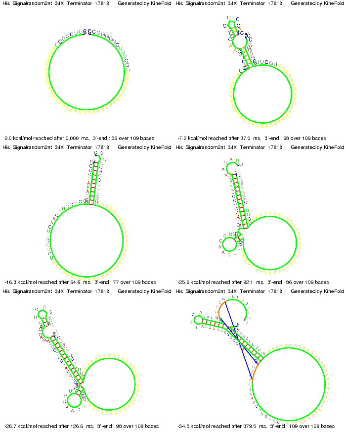
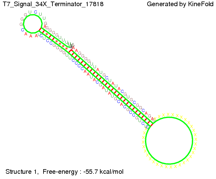
ResultsWe demonstrated that in theoretical simulations the T7-terminator work well. It's less stable than the His-terminator (and rather a lot of bases are unpaired), but its more stable than the Trp-terminator. For appropriate signal length the terminator is not folding at all, that is antitermination occurs. We also demonstrated that a signal length of 8 nt is sufficient for antitermination to happen. Logic gateAfter establishing that our switch works as designed, we combine two switches to build an AND gate an investigate it with further simulations. We used the His-terminator, the Trp-terminator and two corresponding signals with different random signaling parts. Having different signaling parts is necessary, as if one uses the same one in both signals, the AND gate will be transformed into a OR gate and will have the output 'true' even in the case that only one signal is present. We linked all the sequences with a 34 X linker. As above both terminator and signal sequences comprise two and three parts respectively:
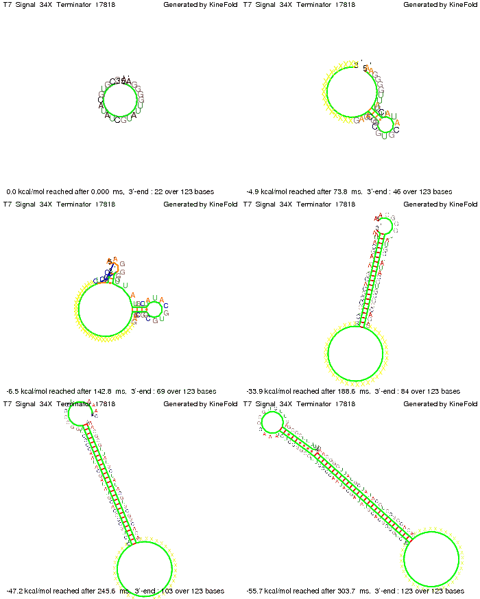
His-terminator sequence 1: We simulated the binding kinetics of the AND gate, created folding path videos which nicely show how the gate is working and applied the results from our signal sequence optimization.
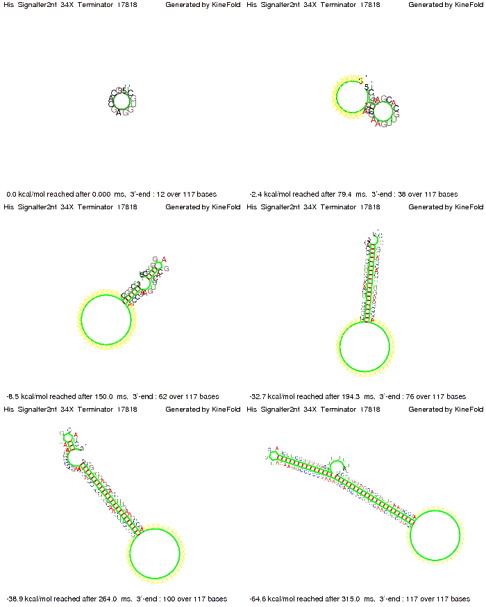
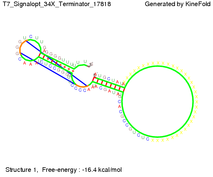
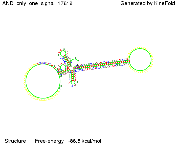
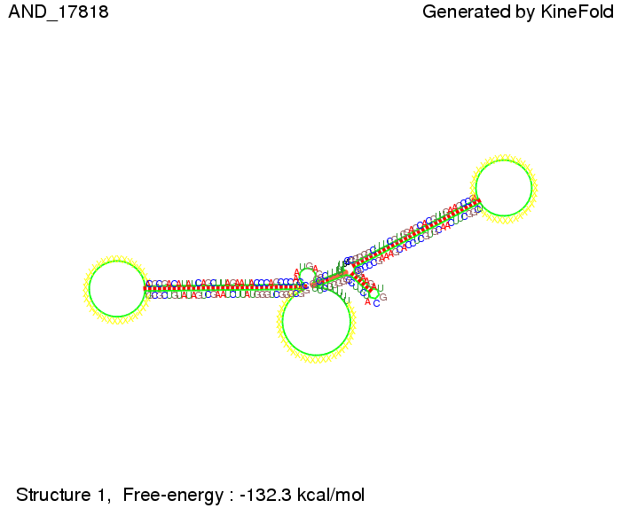
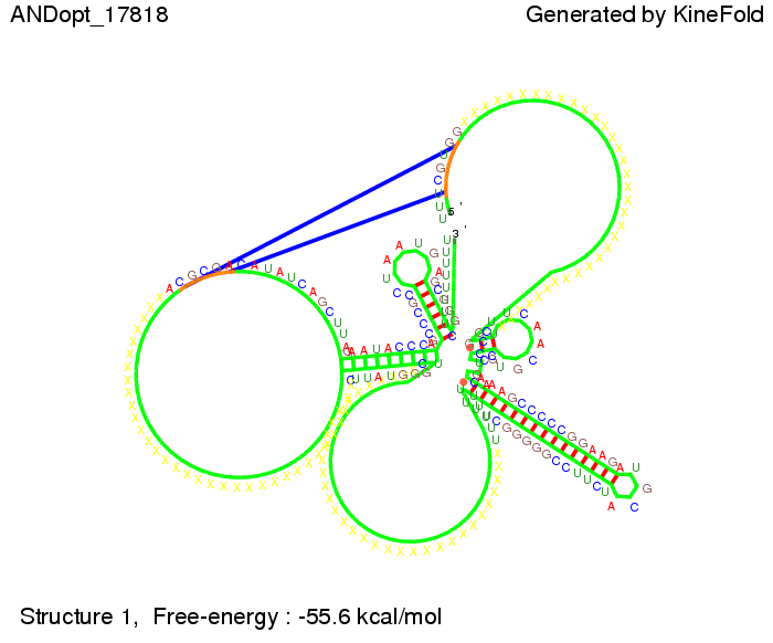
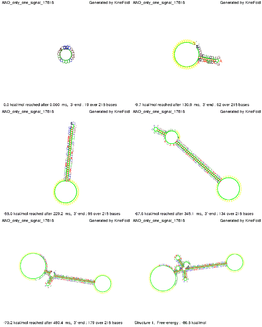
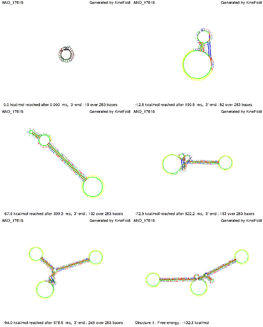
First we considered the case that only one signal sequence is present, that is at most one terminator gets destroyed, which one can see in the picture below. As the picture below displays both of the signals successfully bound to the terminators, thus as both input signals are present (that it both inputs are '1') the AND gate also returns the value '1' as both terminators are destroyed. We also tried to model an AND gate with the optimized signals which were sufficient to destroy a single terminator above, but didn't work out for the AND gate as the picture below shows. The signal sequences were to short to bind to the terminator probably due to hindering by other structures, e.g. by the linker. RNA folding path videosWe created folding path videos for the AND gate. For only one signal present the video shows how the Trp-terminator is not destroyed. On the other hand, when both signals are present, one can see how both signal sequences bind to the terminator sequences as those are synthesized and none of the terminators can fold. CloseResultsWe were able to model a logic gate consisting of two of our switches we introduced above. We proved this logic AND gate to work well, that is if the two input sequences are present the terminators are destroyed and if only one or none signal is present termination occurs. OutlookSo far there is no RNA folding program that is specialized on modeling the interaction of two sequences not to speak of a whole network consisting of RNA based switches and signaling sequences. Combining the concepts of Kinefold[5] and Vienna[6] and using sets of secondary structures that are adjusted to having two sequences instead of only one sequence one could get rid of the bulky linkers. The linkers we used did not play a significant role for our simulation as we were just handling small RNA devices, but for larger networks they are likely to be sterically hindering. This obstacle has to be overcome to allow reliable in silcio modeling of RNA devices. With appropriate software RNA devices like our switches could in future be used to interconnect BioBricks, as demonstrated on our Software page, and to simulate those interconnections at elementary step resolution. References[1] A. Xayaphoummine, T. Bucher and H. Isambert, Kinefold web server for RNA/DNA folding path and structure prediction including pseudoknots and knots, 2005, Nucleic Acids Research, Vol. 33, Web Server issue W605–W610. [2] Berg, v. Hippel, 1985. [3] Doi and Edwards, 1999. The Theory of Polymer Dynamics. [4] Rippe, Making contacts on a nucleic acid polymer, 2001, TRENDS in Biochemical Sciences. [5] A. Xayaphoummine, T. Bucher, F. Thalmann, and H. Isambert, Prediction and statistics of pseudoknots in RNA structures using exactly clustered stochastic simulations, December 23, 2003, 15310–15315 PNAS vol. 100 no. 26. [6] Christoph Flamm, Walter Fontana, Ivo L. Hofacker, and Peter Schuster, RNA folding at elementary step resolution, RNA (2000), 6:325–338 Cambridge University Press. |
|||||||||||||||||||||||||||||||||||||||||||||||||||||||||||||||||||||||||||||||||||||||||||||||||||||
 "
"


