Team:Cambridge/Tools/Eglometer
From 2010.igem.org
(→Shopping list) |
|||
| Line 17: | Line 17: | ||
=Making your own E.glometer= | =Making your own E.glometer= | ||
| - | = | + | <html><h2 style="border-top:0">Shopping list</h2></html> |
There are three core components to make the light detecting device: | There are three core components to make the light detecting device: | ||
* TAOS light to frequency converter - TSL230RP-LF = $6 ('''or''' for higher sensitivity TSL237) | * TAOS light to frequency converter - TSL230RP-LF = $6 ('''or''' for higher sensitivity TSL237) | ||
Latest revision as of 21:27, 27 October 2010

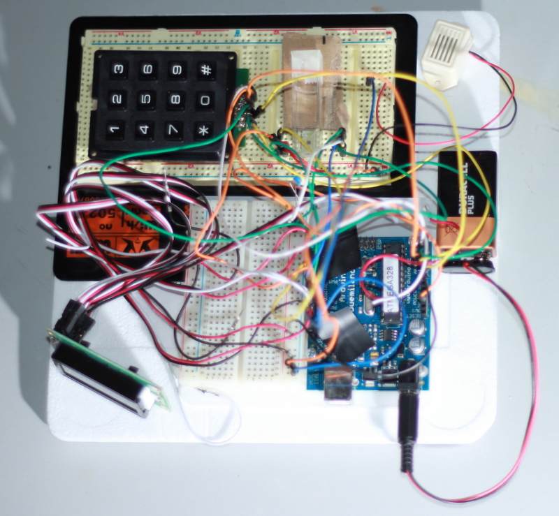
We designed and built a low cost electronic system for measuring light output, this is useful for reporter assays.
Use of the E.glometer
- The user places a culture, or a buffered suspension of cells, in a cuvette
- The cuvette is placed against the TAOS chip
- The device is turned on, it prompts the user for an exposure time. The user enters the time in seconds using the numeric keypad and presses "*" when finished
- The device waits during a 20 second "priming" phase, this is to allow the user to place it in a dark box or cover it well to prevent background light leakage.
- The device counts photons for the period entered, when the time has elapsed it announces this with two beeps.
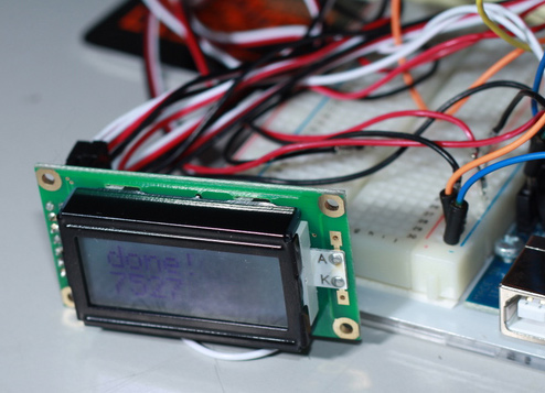
- The number of light units counted is shown on the LCD screen.
Making your own E.glometer
Shopping list
There are three core components to make the light detecting device:- TAOS light to frequency converter - TSL230RP-LF = $6 (or for higher sensitivity TSL237)
- Arduino - $25
- 10 uF capacitor - $0.25
- Total - $31.25

Together these three (and some jump leads) will let you count photons for a well timed period. However you will have to connect a laptop both to report the data collected and to change the exposure time.
We wanted to make a self contained device so we added:
- A numeric keypad - $4.78
- An 8x2 LCD module - $6.62
- A buzzer - to announce completion - $0.80
- A breadboard to allow easy assembly of these components: $10
- Total - $22.20 extra
Wiring
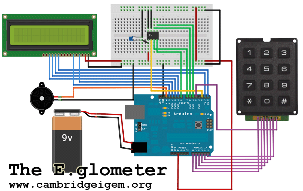
The diagram above shows the connections that should be made on the breadboard. Some LCD screens and keypads may have different pin arrangements. As long as the output pins are updated in the Arduino code a number of permutations are possible.
Arduino code
The code below is designed to run the Arduino in standalone mode. The user enters exposure time, and the Arduino counts photons for this period.
Required libraries [http://www.arduino.cc/playground/Code/Keypad Keypad.h], [http://arduino.cc/en/Reference/LiquidCrystal?from=Tutorial.LCDLibrary LiquidCrystal.h]
//These define the pin connections of the Arduino.
//They can be changed but only use digital in 2 or 3 for the Freq pin
#define TSL_FREQ_PIN 2 // output use digital pin2 for interrupt
#define TSL_S0	     5
#define TSL_S1	     6
#define TSL_S2	     7
#define TSL_S3  8

#include <Keypad.h>  //This is a library which must be downloaded

#include <LiquidCrystal.h> //This is a library which must be downloaded
const byte ROWS = 4; // Four rows
const byte COLS = 3; // Three columns
// Define the Keymap
//This defines the shape of the keypad
char keys[ROWS][COLS] = {
  {'1','2','3'},
  {'4','5','6'},
  {'7','8','9'},
  {'*','0','#'}
};
// Connect keypad ROW0, ROW1, ROW2 and ROW3 to these Arduino pins.
byte rowPins[ROWS] = { 17, 18, 19, 4};
// Connect keypad COL0, COL1 and COL2 to these Arduino pins.
byte colPins[COLS] = { 14, 15, 16 };

// Create the Keypad
Keypad kpd = Keypad( makeKeymap(keys), rowPins, colPins, ROWS, COLS );


// initialize the library with the numbers of the interface pins
LiquidCrystal lcd(11, 12, 0, 1, 9, 10);

unsigned long pulse_cnt = 0;

int getInt(String text)
{
  char temp[20];
  text.toCharArray(temp, 19);
  int x = atoi(temp);
  if (x == 0 && text != "0")
  {
    x = -1;
  }
  return x;
}

void setup() {

  lcd.begin(8, 2);
  lcd.print("test");
  //  Serial.begin(9600);

  // attach interrupt to pin2, send output pin of TSL230R to arduino 2
  // call handler on each rising pulse

  attachInterrupt(0, add_pulse, RISING);

  pinMode(TSL_FREQ_PIN, INPUT);
  pinMode(TSL_S0, OUTPUT);
  pinMode(TSL_S1, OUTPUT);
  pinMode(TSL_S2, OUTPUT);
  pinMode(TSL_S3, OUTPUT);

  digitalWrite(TSL_S0, HIGH);
  digitalWrite(TSL_S1, HIGH);
  digitalWrite(TSL_S2, HIGH);
  digitalWrite(TSL_S3, HIGH);
}

void loop() {
  lcd.setCursor(0, 0);
  lcd.print("Exp.time?");  //Prompt user for exposure time on top line

String displayer="";
boolean moreinput=true;
while(moreinput){
 char key = kpd.getKey();
  if(key)  // same as if(key != NO_KEY)
  {
    switch (key)
    {
      case '*':

        lcd.setCursor(0, 0);
        lcd.print("*"); //submit on "*"
        moreinput=false;
        break;
      case '#':
        lcd.setCursor(0, 0);
        lcd.print("#");
        break;
      default:
      displayer=displayer+key;
        lcd.setCursor(0, 1);
        lcd.print(displayer);
    }
  }
  }
int  timing=getInt(displayer);
 lcd.setCursor(0, 0);
 lcd.print("priming   ");

  for (int i=20; i>0 ; i--){
    lcd.setCursor(0, 1);
    lcd.print(i);
    lcd.print("   ");
    delay(1000);
  }

   lcd.setCursor(0, 0);
 lcd.print("timing   ");
 pulse_cnt=0;

  for (int i=timing; i>0 ; i--){
    lcd.setCursor(0, 1);
    lcd.print(i);
    lcd.print("   ");
    delay(1000);
  }
   lcd.setCursor(0, 0);
 lcd.print("done!");
  int finalcnt=pulse_cnt;
  lcd.setCursor(0, 1);
  lcd.print(finalcnt);
  digitalWrite(13,HIGH);
  delay(500);
  digitalWrite(13,LOW);
  delay(1000);
  digitalWrite(13,HIGH);
  delay(1000);
  digitalWrite(13,LOW);
  delay(1000000);
}

void add_pulse() {

  // increase pulse count
  pulse_cnt++;
  //Serial.println(pulse_cnt);
  return;
}
- The code above incorporates code from [http://roamingdrone.wordpress.com/2008/11/28/arduino-and-the-tsl230r-photographic-conversions/ C. Church] licensed under a Creative Commons license.
- It can be extended to allow data logging to a laptop via serial port, or to display further calculations based on the raw data.
 "
"


