Team:Stanford/Research
From 2010.igem.org
(→The First Design) |
(→Flow Cytometry Data) |
||
| (27 intermediate revisions not shown) | |||
| Line 8: | Line 8: | ||
The Stanford team's ratio sensors use biological machinery to eliminate the human component from ratio computation. Our output system is more efficient than two individual sensors and, most importantly, can pass its results on to other parts and devices. A ratio sensor performs a calculation that a user doesn't need to/won't be able to. A ratio sensor frees up a wavelength channel on the measurement device, and, more importantly for the future, allows the computed ratio to be passed on to another part. A useful ratio sensor that could be utilized in a broad regime of biological applications needs to be operable and accurate in micro-environments; the Stanford team's ratio sensor is engineered to function within E. Coli, which is fully operable over a range of environments. | The Stanford team's ratio sensors use biological machinery to eliminate the human component from ratio computation. Our output system is more efficient than two individual sensors and, most importantly, can pass its results on to other parts and devices. A ratio sensor performs a calculation that a user doesn't need to/won't be able to. A ratio sensor frees up a wavelength channel on the measurement device, and, more importantly for the future, allows the computed ratio to be passed on to another part. A useful ratio sensor that could be utilized in a broad regime of biological applications needs to be operable and accurate in micro-environments; the Stanford team's ratio sensor is engineered to function within E. Coli, which is fully operable over a range of environments. | ||
| - | |||
==Our Project: Two Designs for Ratio Detection== | ==Our Project: Two Designs for Ratio Detection== | ||
Our team decided to pursue two different systems for detecting ratios. After considering the scenarios in which biological engineers would want to use ratio sensors, having two specialized sensors seemed to allow greater flexibility of usage than a single design. | Our team decided to pursue two different systems for detecting ratios. After considering the scenarios in which biological engineers would want to use ratio sensors, having two specialized sensors seemed to allow greater flexibility of usage than a single design. | ||
| - | While both systems receive two input signals, the output they give is different, allowing them be applied in different situations. Here's a brief rundown of the two designs (you can see more by clicking through to the individual project pages). | + | While both systems receive two input signals, the output they give is different, allowing them be applied in different situations. Here's a brief rundown of the two designs (you can see more by clicking through to the individual project pages). '''Both sensors are: (1) ''Modular'': input and output molecules can be changed without affecting the interior mechanism of the device; and (2) ''Orthogonal'': device mechanisms are not found in E. coli, avoid crosstalk with host cell''' |
| - | + | ||
| - | + | ||
| + | ==Our First Sensor: The sRNA Sensor== | ||
| + | ====Device Properties==== | ||
'''Method''': Small RNA Interference | '''Method''': Small RNA Interference | ||
| Line 25: | Line 24: | ||
'''Data''': Initial data gathered using FACS on part K353002, along with a more detailed description of our sRNA interference design can be found below. | '''Data''': Initial data gathered using FACS on part K353002, along with a more detailed description of our sRNA interference design can be found below. | ||
| - | ===Overview=== | + | ====Overview==== |
Our first sensor design is tuned to a '''single ratio''' of input chemicals and tells the user if the input chemicals are present in relative concentrations '''below''', '''at''', or '''above''' that ratio. | Our first sensor design is tuned to a '''single ratio''' of input chemicals and tells the user if the input chemicals are present in relative concentrations '''below''', '''at''', or '''above''' that ratio. | ||
| Line 39: | Line 38: | ||
By engineering readout redundancy into the sRNA sensor, we have insulated our sensor from detector-specific readout noise. If there were only one color, we would register the transition from off -> on whenever the signal exceeded the signal/noise ratio of our detector. This means that we would actually read the off/on transition as occurring at different points in the input domain with different detectors! But with two colors, (one transitioning from off -> on, the other from on -> off), we can set the detection threshold far above our detector's S/N threshold, and average the transition point in the two channels to achieve a detector-independent measurement of the specified ratio. | By engineering readout redundancy into the sRNA sensor, we have insulated our sensor from detector-specific readout noise. If there were only one color, we would register the transition from off -> on whenever the signal exceeded the signal/noise ratio of our detector. This means that we would actually read the off/on transition as occurring at different points in the input domain with different detectors! But with two colors, (one transitioning from off -> on, the other from on -> off), we can set the detection threshold far above our detector's S/N threshold, and average the transition point in the two channels to achieve a detector-independent measurement of the specified ratio. | ||
| - | + | You can read about our other sensor [[Team:Stanford/Analog Sensor|here]] . | |
| - | ===The RSID: Improving sRNA Interference=== | + | ====The RSID: Improving sRNA Interference==== |
Our system uses sRNA interference, which is usually a non-modular operation. Because each sRNA must be complementary to the mRNA sequence of the protein it inactivates, changing outputs in a traditional sRNA interference system would require designing and inserting a new sRNA for each output. To overcome this design flaw and make our sensor more easily modified, we implemented a novel control system for sRNA interference: the RSID. | Our system uses sRNA interference, which is usually a non-modular operation. Because each sRNA must be complementary to the mRNA sequence of the protein it inactivates, changing outputs in a traditional sRNA interference system would require designing and inserting a new sRNA for each output. To overcome this design flaw and make our sensor more easily modified, we implemented a novel control system for sRNA interference: the RSID. | ||
| Line 53: | Line 52: | ||
Our RSID's are valuable parts in their own right, as they can be applied to any other projects employing sRNA interference to yield similar modularity and precision targeting. | Our RSID's are valuable parts in their own right, as they can be applied to any other projects employing sRNA interference to yield similar modularity and precision targeting. | ||
| + | ====Device and Parts Level Diagrams==== | ||
| - | + | [[Image:sRNADevice.jpg | 700px | A device-level diagram of our sRNA-based sensor ]]<br> | |
| - | + | ||
| - | + | ||
| - | [[Image:sRNADevice.jpg | 700px | A device-level diagram of our sRNA-based sensor]]<br> | + | |
(1) Input A activates Receiver and Reporter 1. (2) Input B activates Receiver and Reporter 2. (3) There is more input A, so Receiver and Reporter 1 will strongly repress Receiver and Reporter 2. (4) There is less input B, so the repression going the other way is weaker. (5) This leads to the production of output A, and (6) little to no production of output B. (7) The output of the device is either dominated by output A or output B. By seeing which is the case, we can infer whether input A or input B was present in greater amounts. | (1) Input A activates Receiver and Reporter 1. (2) Input B activates Receiver and Reporter 2. (3) There is more input A, so Receiver and Reporter 1 will strongly repress Receiver and Reporter 2. (4) There is less input B, so the repression going the other way is weaker. (5) This leads to the production of output A, and (6) little to no production of output B. (7) The output of the device is either dominated by output A or output B. By seeing which is the case, we can infer whether input A or input B was present in greater amounts. | ||
| Line 63: | Line 60: | ||
(1) Input A leads to the transcription of (2) GFP mRNA and (3) sRNA targeting RFP mRNA. This is how we implement both reporting and repressing outputs as a result of sengins input A. (4) Input B leads to two similar transcription events: (5) RFP mRNA and (6) sRNA targeting GFP mRNA. In this scenario, because there is more input A than input B, the GFP mRNA is translated whereas the RFP mRNA is silenced by its respective sRNA, thus leading to (7) a device output that is clearly more green than red, reflecting the relative levels of input A to input B. <br><br> | (1) Input A leads to the transcription of (2) GFP mRNA and (3) sRNA targeting RFP mRNA. This is how we implement both reporting and repressing outputs as a result of sengins input A. (4) Input B leads to two similar transcription events: (5) RFP mRNA and (6) sRNA targeting GFP mRNA. In this scenario, because there is more input A than input B, the GFP mRNA is translated whereas the RFP mRNA is silenced by its respective sRNA, thus leading to (7) a device output that is clearly more green than red, reflecting the relative levels of input A to input B. <br><br> | ||
| - | ===Flow Cytometry Data=== | + | ====Flow Cytometry Data==== |
| - | + | Below is a graph of our flow cytometry data for part K353002 plotting GFP output for BW27783 cells: | |
| - | [[Image:realdata.jpg| | + | [[Image:realdata.jpg|center]] <br> |
Both of these graphs plot the output of part K353002 in BW27783 cells induced with a series of concentrations of L-arabinose, measured in molarity. The first is a histogram showing the distribution of expression levels at each concentration of L-arabinose. The second is the same data displayed as a cumulative distribution so that population medians are more apparent. | Both of these graphs plot the output of part K353002 in BW27783 cells induced with a series of concentrations of L-arabinose, measured in molarity. The first is a histogram showing the distribution of expression levels at each concentration of L-arabinose. The second is the same data displayed as a cumulative distribution so that population medians are more apparent. | ||
| Line 74: | Line 71: | ||
*Fold Induction: 860 | *Fold Induction: 860 | ||
| - | + | ==The Second Design: Kinase Phosphatase System== | |
| + | |||
| + | ====Device Properties==== | ||
'''Method''': Kinase/Phosphatase Regulation of a Transcription Factor | '''Method''': Kinase/Phosphatase Regulation of a Transcription Factor | ||
| Line 88: | Line 87: | ||
*http://partsregistry.org/Part:BBa_K353008 | *http://partsregistry.org/Part:BBa_K353008 | ||
| - | ''' | + | ====Overview==== |
| - | + | ||
| - | + | Our second sensor design responds to a '''range of ratios''', varying the '''intensity of the output''' to indicate the ratio of input chemicals. | |
| + | |||
| + | One of the input chemicals leads to the phosphorylation of a transcription factor, while the other leads to its de-phosphorylation. Only the phosphorylated version of the transcription factor can activate the promoter upstream of the output protein. Visit our [[Team:Stanford/Research/Modeling| modeling]] page to read about how the ratio of the two inputs can be computed as a linear function of the output. | ||
| + | |||
| + | uses a transcription factor regulated by a kinase/phosphotase pair. In this system, the phosphorylated form of the transcription factor causes transcription of a gene coding for our output protein. The production of the transcription factor is under the control of a constitutive promoter, which maintains a basal concentration. The kinase that acts on the transcription factor is under the control of a promoter positively regulated by A. A phosphotase is similarly controlled by input B. By testing the concentration of output protein in relation to various concentrations of input chemicals, we plan to create an algorithm that will allow us to work backwards from a given concentration of output protein to deduce the ratio of the original concentrations of input chemicals. | ||
| + | |||
| + | Read about our [[Team:Stanford/Digital Sensor|other sensor]] or return to our [[Team:Stanford/Research|project]] page. | ||
| + | |||
| + | ====Device and Parts Level Diagrams==== | ||
| + | |||
| + | [[Image:EnzymePairDevice.jpg | 700px | caption]] | ||
| + | <br>Input A '''(1)''' activates receiver 1 '''(3)''', which activates the reporter '''(5)''', causing synthesis of the output protein '''(6)'''. | ||
| + | |||
| + | Input B '''(2)''' activates receiver 2 '''(4)''', which inactivates the reporter '''(5)''', decreasing synthesis of the output protein '''(6)'''. | ||
| + | |||
| + | [[Image:Slide12.jpg| 700px | caption]] | ||
| + | <br>Part K353007 is under the control of R0040, so there is always some basal level of transcription factor present within the cell. | ||
| + | L-arabinose binds to I0500, causing transcription of K353005, which phosphorylates the transcription factor K353007, allowing it to bind and activate K353008 (reporter). | ||
| + | AHL binds to F2620, activating transcription of K353006, which removes the phosphate group from the the transcription factor (K353007), inactivating it and preventing it from binding K353008. | ||
| - | + | ==Ratios: Better than Absolutes== | |
| - | =Ratios: Better than Absolutes= | + | |
Why did we go to the trouble of developing sensors to detect ratios when so many already exist to detect absolute concentrations? Because '''ratios are better.''' | Why did we go to the trouble of developing sensors to detect ratios when so many already exist to detect absolute concentrations? Because '''ratios are better.''' | ||
| Line 101: | Line 117: | ||
Our unified sensor is also better than simply combining two absolute sensors into a single cell and comparing the outputs. Besides requiring the cell to produce fewer proteins (freeing up cell energy for other processes), our approach significantly reduces output noise. Additionally, a two-output system requires a human observer to take readings and make a decision. Our system can be hooked up straight to an output protein, allowing a rapid in-vivo response. | Our unified sensor is also better than simply combining two absolute sensors into a single cell and comparing the outputs. Besides requiring the cell to produce fewer proteins (freeing up cell energy for other processes), our approach significantly reduces output noise. Additionally, a two-output system requires a human observer to take readings and make a decision. Our system can be hooked up straight to an output protein, allowing a rapid in-vivo response. | ||
| - | ==Project Goals== | + | ===Project Goals=== |
| - | ===Digital Sensor=== | + | ====Digital Sensor==== |
*Accurately report whether the concentrations of input chemicals lie at, above, or below a given ratio | *Accurately report whether the concentrations of input chemicals lie at, above, or below a given ratio | ||
*Allow as little expression as possible at the detection ratio, and as much as possible at all other ratios | *Allow as little expression as possible at the detection ratio, and as much as possible at all other ratios | ||
| - | ===Analog Sensor=== | + | ====Analog Sensor==== |
*Accurately report over a large range of input ratios | *Accurately report over a large range of input ratios | ||
*Achieve a linear correlation between output protein concentration and detection ratio | *Achieve a linear correlation between output protein concentration and detection ratio | ||
*Have a low basal level of expression | *Have a low basal level of expression | ||
| - | ===Both Sensors=== | + | ====Both Sensors==== |
*Allow future users to change output proteins and input promoters without disrupting the sensor's internal machinery | *Allow future users to change output proteins and input promoters without disrupting the sensor's internal machinery | ||
*Have both sensors be orthogonal to the host system to avoid cross-talk | *Have both sensors be orthogonal to the host system to avoid cross-talk | ||
| - | ==Important Parameters== | + | ===Important Parameters=== |
| - | ===Digital Sensor=== | + | ====Digital Sensor==== |
#Range of possible ratios | #Range of possible ratios | ||
| Line 127: | Line 143: | ||
#Response time | #Response time | ||
| - | ===Analog Sensor=== | + | ====Analog Sensor==== |
#Range of possible ratios | #Range of possible ratios | ||
Latest revision as of 03:54, 28 October 2010

| Home | Project | Applications | Modeling | Parts | Team | Notebook |
Contents |
Why Ratios?
Ratios rule the biological world, and controlling them will unlock a vast range of applications for synthetic biology.
In electrical and mechanical engineering, computers can be used to calculate a ratio from precise measurements, but biological engineering doesn't have that luxury. We need a hardwired device to compute and act on ratios independent of a controlling computer or human researcher.
The Stanford team's ratio sensors use biological machinery to eliminate the human component from ratio computation. Our output system is more efficient than two individual sensors and, most importantly, can pass its results on to other parts and devices. A ratio sensor performs a calculation that a user doesn't need to/won't be able to. A ratio sensor frees up a wavelength channel on the measurement device, and, more importantly for the future, allows the computed ratio to be passed on to another part. A useful ratio sensor that could be utilized in a broad regime of biological applications needs to be operable and accurate in micro-environments; the Stanford team's ratio sensor is engineered to function within E. Coli, which is fully operable over a range of environments.
Our Project: Two Designs for Ratio Detection
Our team decided to pursue two different systems for detecting ratios. After considering the scenarios in which biological engineers would want to use ratio sensors, having two specialized sensors seemed to allow greater flexibility of usage than a single design.
While both systems receive two input signals, the output they give is different, allowing them be applied in different situations. Here's a brief rundown of the two designs (you can see more by clicking through to the individual project pages). Both sensors are: (1) Modular: input and output molecules can be changed without affecting the interior mechanism of the device; and (2) Orthogonal: device mechanisms are not found in E. coli, avoid crosstalk with host cell
Our First Sensor: The sRNA Sensor
Device Properties
Method: Small RNA Interference
Output: One of two possible proteins, depending on whether the ratio of input chemicals lies above or below a predetermined threshold
Useful: For reporting on a situation with a boolean output: disease detection, preterm labor warning, cancer metastasis warning
Data: Initial data gathered using FACS on part K353002, along with a more detailed description of our sRNA interference design can be found below.
Overview
Our first sensor design is tuned to a single ratio of input chemicals and tells the user if the input chemicals are present in relative concentrations below, at, or above that ratio.
L-arabinose binds to pBAD (BBa_I0500) which promotes the transcription of sRNA2, RSID1, and GFP. AHL binds to pLUX (BBa_F2620), which promotes the transcription of sRNA1, RSID2, and RFP. In the cytoplasm, each sRNA binds to its respective RSID before translation occurs. Ribosomes are prevented from binding to those mRNA's that are bound by sRNA's, meaning that only those mRNA's that remain unbound by sRNA's get translated into reporter protein. sRNA/mRNA dimers are eventually degraded by the cell's machinery.
If the concentration of L-arabinose is greater than that of AHL, more sRNA2 and GFP will be produced than sRNA1 and RFP. This means that each sRNA1 will be able to bind to a copy of RSID1, while there will not be enough sRNA2 to inhibit all of the RFP. An excess of L-arabinose therefore leads to an expression of GFP.
To change the threshold ratio detected by the sensor, multiple copies of the genes encoding either the mRNA or the sRNA can be placed downstream of the promoters.
By sensing only one ratio, we gain a sharp transition between no signal and a lot of signal. This allows us to insulate our output from biological noise in all regimes of the input domain except for the small neighborhood surrounding the sharp transition.
By engineering readout redundancy into the sRNA sensor, we have insulated our sensor from detector-specific readout noise. If there were only one color, we would register the transition from off -> on whenever the signal exceeded the signal/noise ratio of our detector. This means that we would actually read the off/on transition as occurring at different points in the input domain with different detectors! But with two colors, (one transitioning from off -> on, the other from on -> off), we can set the detection threshold far above our detector's S/N threshold, and average the transition point in the two channels to achieve a detector-independent measurement of the specified ratio.
You can read about our other sensor here .
The RSID: Improving sRNA Interference
Our system uses sRNA interference, which is usually a non-modular operation. Because each sRNA must be complementary to the mRNA sequence of the protein it inactivates, changing outputs in a traditional sRNA interference system would require designing and inserting a new sRNA for each output. To overcome this design flaw and make our sensor more easily modified, we implemented a novel control system for sRNA interference: the RSID.
The RSID is a synthetically-created DNA sequence that includes a ribosome binding site, and is inserted upstream of the output proteins. Each sRNA recognizes and binds to a specific RSID, covering the RBS contained within it and preventing the translation of the downstream output protein.
Because the RSID's are independent from the output protein, new output proteins may be inserted without affecting the performance or design of the internal mechanism. This feature allows our system to be modified by future users to release any necessary output protein.
In choosing the sequence of our RSID's and sRNA's, we were careful to avoid several possible pitfalls. Our sRNA's and RSID's are all non-complementary to anything in the host cell's genome in order to avoid accidentally inhibiting important cell processes. In addition, we screened our designs to make sure they had low levels of self-dimerization, which would limit their effectiveness.
Our RSID's are valuable parts in their own right, as they can be applied to any other projects employing sRNA interference to yield similar modularity and precision targeting.
Device and Parts Level Diagrams
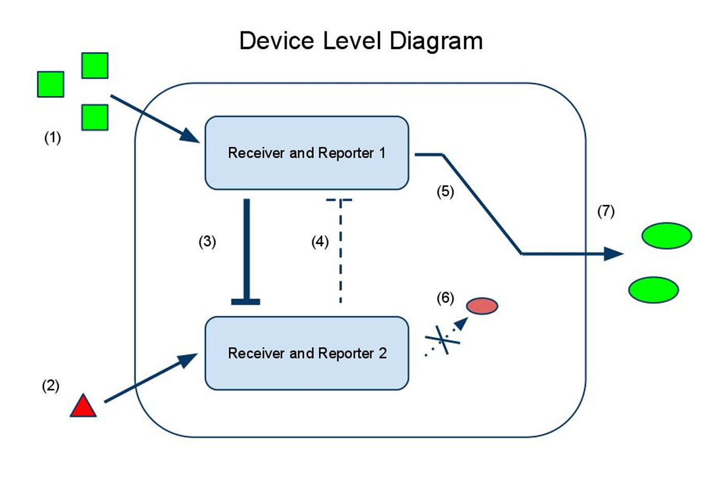
(1) Input A activates Receiver and Reporter 1. (2) Input B activates Receiver and Reporter 2. (3) There is more input A, so Receiver and Reporter 1 will strongly repress Receiver and Reporter 2. (4) There is less input B, so the repression going the other way is weaker. (5) This leads to the production of output A, and (6) little to no production of output B. (7) The output of the device is either dominated by output A or output B. By seeing which is the case, we can infer whether input A or input B was present in greater amounts.
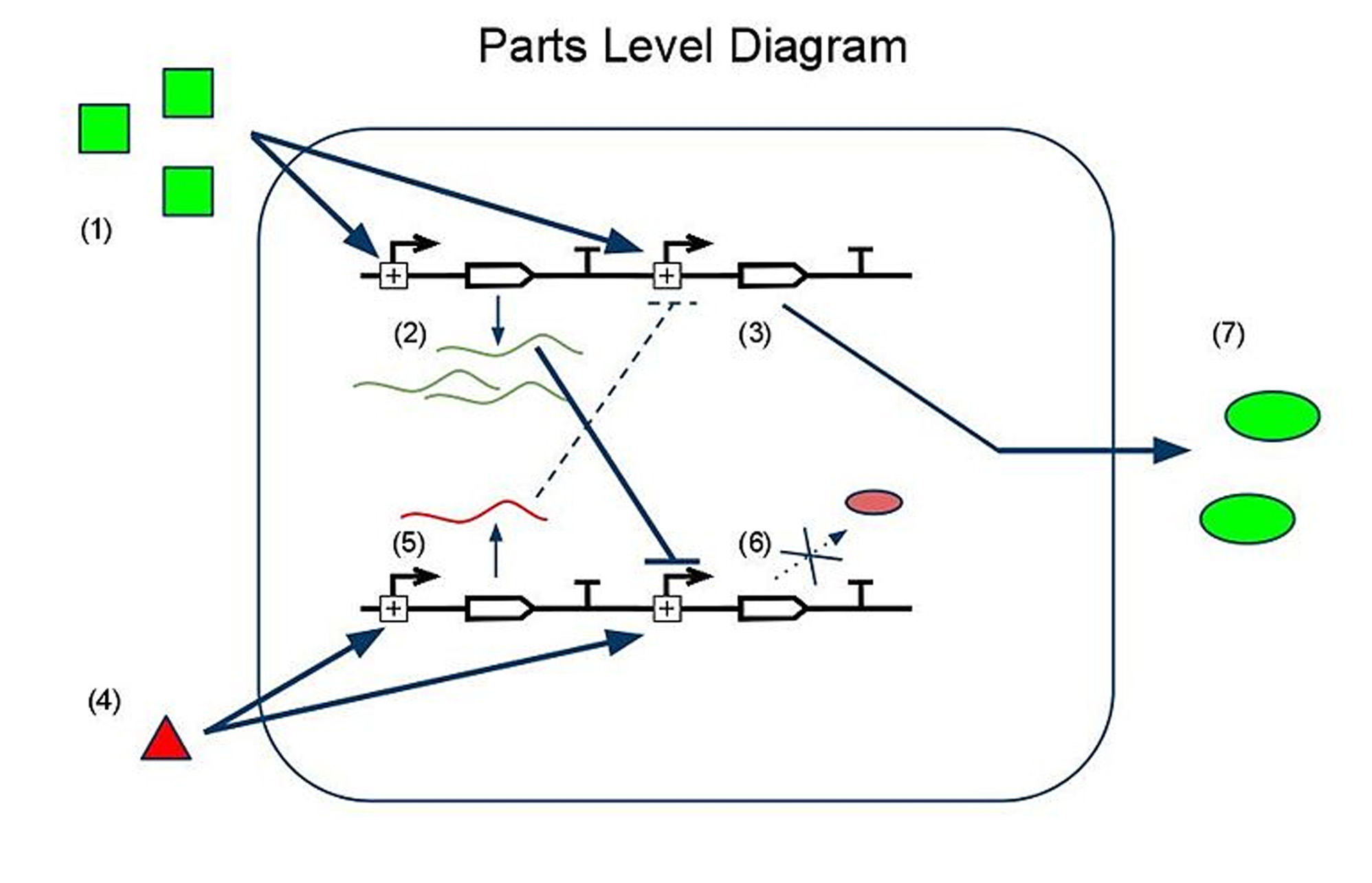
(1) Input A leads to the transcription of (2) GFP mRNA and (3) sRNA targeting RFP mRNA. This is how we implement both reporting and repressing outputs as a result of sengins input A. (4) Input B leads to two similar transcription events: (5) RFP mRNA and (6) sRNA targeting GFP mRNA. In this scenario, because there is more input A than input B, the GFP mRNA is translated whereas the RFP mRNA is silenced by its respective sRNA, thus leading to (7) a device output that is clearly more green than red, reflecting the relative levels of input A to input B.
Flow Cytometry Data
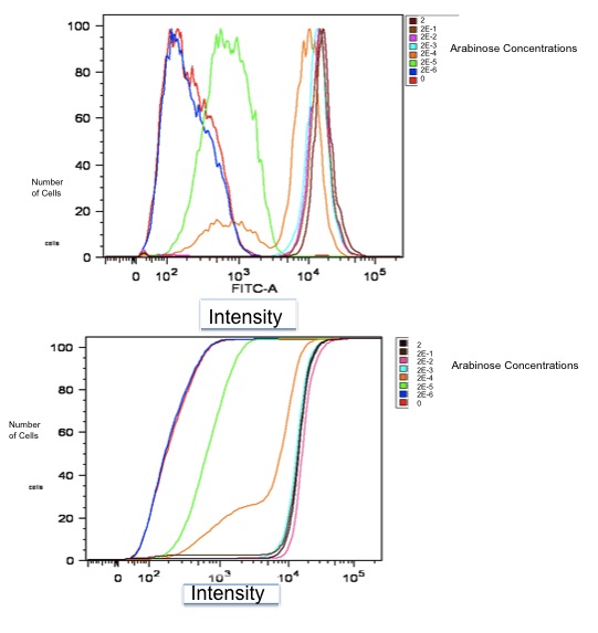
Below is a graph of our flow cytometry data for part K353002 plotting GFP output for BW27783 cells:
Both of these graphs plot the output of part K353002 in BW27783 cells induced with a series of concentrations of L-arabinose, measured in molarity. The first is a histogram showing the distribution of expression levels at each concentration of L-arabinose. The second is the same data displayed as a cumulative distribution so that population medians are more apparent.
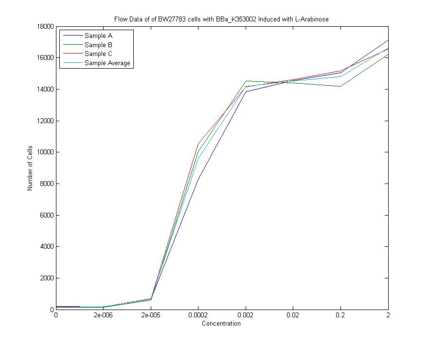
We measured a dose-response-curve of median output vs L-arabinose concentration in triplicate. This curve constitutes the basic characterization of part K353002, including measurement of the concentration of L-arabinose which gives half-maximal output, the steepness of transition from off to on, and the parts dynamic range. Fitting a Hill curve provided the following values plus or minus 95% confidence intervals:
- Half-max induction: 143 +- 36 uM
- Hill coefficient: 1.4 +- .6
- Fold Induction: 860
The Second Design: Kinase Phosphatase System
Device Properties
Method: Kinase/Phosphatase Regulation of a Transcription Factor
Output: One output protein whose concentration is linearly dependent on the ratio of the input chemicals
Useful: For acting in a situation requiring a graded response: drug delivery, metabolic flux control, detailed ratiometric reporting
Data: Please refer to the following pages for data:
- http://partsregistry.org/Part:BBa_K353005
- http://partsregistry.org/Part:BBa_K353006
- http://partsregistry.org/Part:BBa_K353007
- http://partsregistry.org/Part:BBa_K353008
Overview
Our second sensor design responds to a range of ratios, varying the intensity of the output to indicate the ratio of input chemicals.
One of the input chemicals leads to the phosphorylation of a transcription factor, while the other leads to its de-phosphorylation. Only the phosphorylated version of the transcription factor can activate the promoter upstream of the output protein. Visit our modeling page to read about how the ratio of the two inputs can be computed as a linear function of the output.
uses a transcription factor regulated by a kinase/phosphotase pair. In this system, the phosphorylated form of the transcription factor causes transcription of a gene coding for our output protein. The production of the transcription factor is under the control of a constitutive promoter, which maintains a basal concentration. The kinase that acts on the transcription factor is under the control of a promoter positively regulated by A. A phosphotase is similarly controlled by input B. By testing the concentration of output protein in relation to various concentrations of input chemicals, we plan to create an algorithm that will allow us to work backwards from a given concentration of output protein to deduce the ratio of the original concentrations of input chemicals.
Read about our other sensor or return to our project page.
Device and Parts Level Diagrams
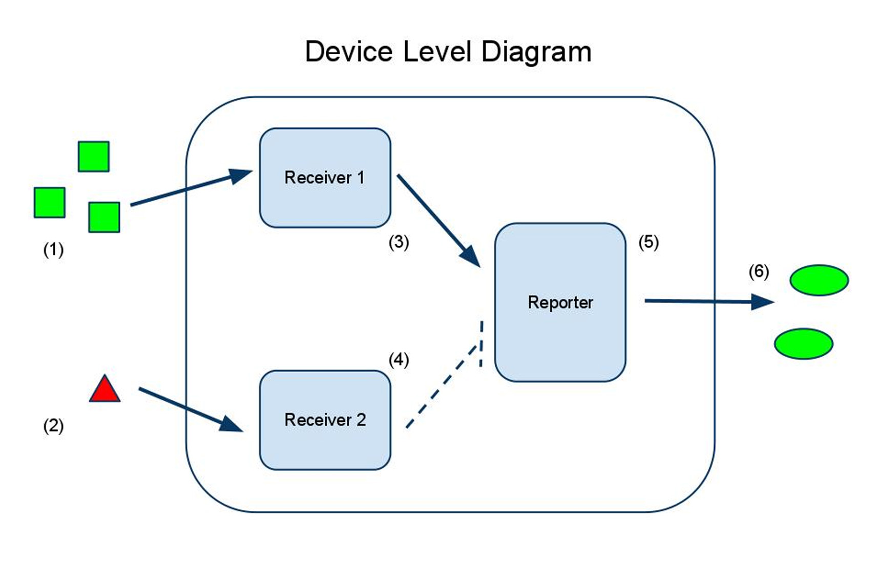
Input A (1) activates receiver 1 (3), which activates the reporter (5), causing synthesis of the output protein (6).
Input B (2) activates receiver 2 (4), which inactivates the reporter (5), decreasing synthesis of the output protein (6).
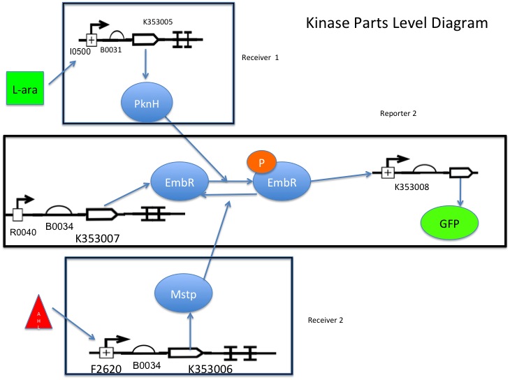
Part K353007 is under the control of R0040, so there is always some basal level of transcription factor present within the cell.
L-arabinose binds to I0500, causing transcription of K353005, which phosphorylates the transcription factor K353007, allowing it to bind and activate K353008 (reporter).
AHL binds to F2620, activating transcription of K353006, which removes the phosphate group from the the transcription factor (K353007), inactivating it and preventing it from binding K353008.
Ratios: Better than Absolutes
Why did we go to the trouble of developing sensors to detect ratios when so many already exist to detect absolute concentrations? Because ratios are better.
For many biological processes, absolute concentrations vary with time or environmental conditions. A sensor detecting the absolute concentration of a biologically significant molecule would respond to these fluctuations, creating systemic noise and false results. Our sensors can detect a "normalized" version of the molecule's concentration by comparing it to a different molecule whose regular cycles are similar.
Our unified sensor is also better than simply combining two absolute sensors into a single cell and comparing the outputs. Besides requiring the cell to produce fewer proteins (freeing up cell energy for other processes), our approach significantly reduces output noise. Additionally, a two-output system requires a human observer to take readings and make a decision. Our system can be hooked up straight to an output protein, allowing a rapid in-vivo response.
Project Goals
Digital Sensor
- Accurately report whether the concentrations of input chemicals lie at, above, or below a given ratio
- Allow as little expression as possible at the detection ratio, and as much as possible at all other ratios
Analog Sensor
- Accurately report over a large range of input ratios
- Achieve a linear correlation between output protein concentration and detection ratio
- Have a low basal level of expression
Both Sensors
- Allow future users to change output proteins and input promoters without disrupting the sensor's internal machinery
- Have both sensors be orthogonal to the host system to avoid cross-talk
Important Parameters
Digital Sensor
- Range of possible ratios
- Background expression level
- Of both proteins at desired ratio
- Of either protein when it shouldn't be being expressed
- Response curve
- Response time
Analog Sensor
- Range of possible ratios
- Background expression level (no kinase-inducing chemical added)
- Phosphotase specificity
- Response curve
- Response time
-->
Biosafety
1. Would any of your project ideas raise safety issues in terms of researcher safety, public safety, or environmental safety?
Answer: There are no major safety risks regarding our general system design. In its current form, our device is only meant for ratiometric analysis of compounds within E. coli. As with any other biological hazard, typical laboratory precaution should be taken when handling cells resistant against antibiotics.
2. Is there a local biosafety group, committee, or review board at your institution?
Answer: There is a local board at Stanford University called Health and Safety at the Stanford University School of Medicine.
3. What does your local biosafety group think about your project?
Answer: We have not communicated with our local biosafety group regarding the design or safety of our project.
4. Do any of the new BioBrick parts that you made this year raise any safety issues?
Answer: Although the kinases and phosphatases chosen for our project come from Mycobacterium tuberculosis and Streptomyces coelicolor A3(2), our team advisors and graduate mentors believe that these proteins do not pose any significant safety risks.
Research
Medal Requirements
Bronze Medal
- Register the team, have a great summer, and have fun attending the Jamboree.
- Done!
- Successfully complete and submit a Project Summary form.
- Done!
- Create and share a Description of the team's project via the iGEM wiki
- Present a Poster and Talk at the iGEM Jamboree
- Booked our plane tickets!
- Enter information detailing at least one new standard BioBrick Part or Device in the Registry of Parts
- [http://partsregistry.org/wiki/index.php?title=Part:BBa_K353002 Done!]
- Entered information for each new part or device should at least include primary nucleic acid sequence, description of function, authorship, any relevant safety notes, and an acknowledgement of sources and references.
- [http://partsregistry.org/wiki/index.php?title=Part:BBa_K353002 Done!]
- Submit DNA for at least one new BioBrick Part or Device to the Registry of Parts.
- Done!
Silver Medal
- Demonstrate that at least one new BioBrick Part or Device of your own design and construction works as expected.
- Characterize the operation of at least one new BioBrick Part or Device and enter this information on the Parts or Device page via the Registry of Parts
Gold Medal
- Characterize or improve an existing BioBrick Part or Device and enter this information back on the Registry.
- When sequencing one of our ligations, we noticed an unexpected sequence in our results. After more investigation, we determined that that sequence came from the Distribution part [http://partsregistry.org/wiki/index.php?title=Part:BBa_E1010 BBa_E1010], and that the part sequence listed on the Parts Registry was incomplete. We have notified the Registry and made a note of this discovery on the E1010 parts experience page.
- Outlined and detailed a new approach to an issue of Human Practice in synthetic biology as it relates to your project, such as safety, security, ethics, or ownership, sharing, and innovation.
- With our Twitter project, we hope to help all iGEM teams by facilitating collaboration (i.e. sharing of data and inducing innovation) between teams. Read more about it here!
 "
"

