Team:Johns Hopkins/Notebook
From 2010.igem.org
(→Microfluidics) |
(→Characterization Of CDRE-RFP system in wild type yeast and PMC1-YFP system in knockout yeast) |
||
| (26 intermediate revisions not shown) | |||
| Line 17: | Line 17: | ||
{ | { | ||
display:block; | display:block; | ||
| - | width: | + | width:112px; |
font-weight:bold; | font-weight:bold; | ||
color:#FFFFFF; | color:#FFFFFF; | ||
| Line 39: | Line 39: | ||
<li><a href="https://2010.igem.org/Team:Johns_Hopkins/Modeling">Modeling</a></li> | <li><a href="https://2010.igem.org/Team:Johns_Hopkins/Modeling">Modeling</a></li> | ||
<li><a href="https://2010.igem.org/Team:Johns_Hopkins/Parts">Parts</a></li> | <li><a href="https://2010.igem.org/Team:Johns_Hopkins/Parts">Parts</a></li> | ||
| + | <li><a href="https://2010.igem.org/Team:Johns_Hopkins/Device">Device</a></li> | ||
<li><a href="https://2010.igem.org/Team:Johns_Hopkins/Notebook">Notebook</a></li> | <li><a href="https://2010.igem.org/Team:Johns_Hopkins/Notebook">Notebook</a></li> | ||
<li><a href="https://2010.igem.org/Team:Johns_Hopkins/Safety">Safety</a></li> | <li><a href="https://2010.igem.org/Team:Johns_Hopkins/Safety">Safety</a></li> | ||
| Line 44: | Line 45: | ||
</body> | </body> | ||
</html> | </html> | ||
| - | |||
| - | |||
| - | |||
| - | |||
| - | |||
| - | |||
| - | |||
| - | |||
| - | |||
| - | |||
| - | |||
| - | |||
| - | |||
| - | |||
| - | |||
| - | |||
| - | |||
| - | |||
| - | |||
| - | |||
| - | |||
| - | |||
| - | |||
| - | |||
==Experiments== | ==Experiments== | ||
| Line 81: | Line 58: | ||
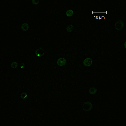
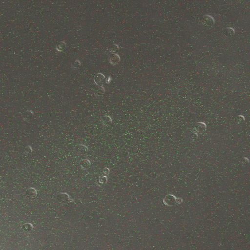
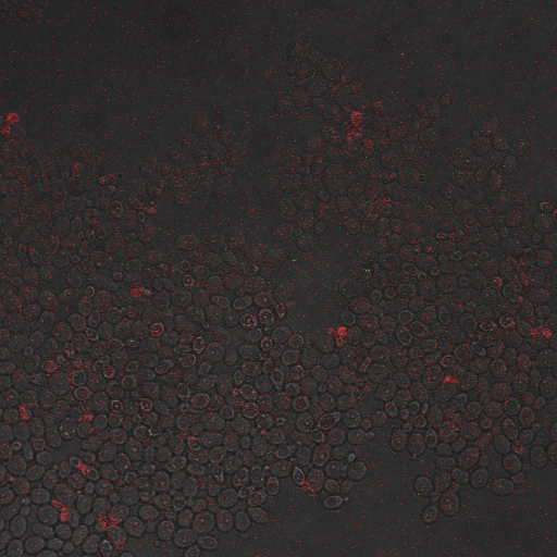
Representative images: | Representative images: | ||
| - | + | {| | |
| - | ====Conclusions and discussion | + | |[[Image:CRZ_GFP.jpg|200px|thumb|Yeast expressing Crz1-GFP]] |
| + | |[[Image:CRZ_GFP_2.jpg|200px|thumb|Similar picture of Crz1-GFP expression]] | ||
| + | |} | ||
| + | ====Conclusions and discussion==== | ||
From this experiment it is clear that there is a calcium influx into the cell on application of a voltage across the cell membrane. We have also established that there is a significant influx of Crz1 into the nucleus associated with this calcium influx as we expected. We hypothesis that the reason we saw Crz1 nuclear localisation only in cells very close to the live electrode because the voltage provided by the function generator was too low to reach across the gap, and so a hypothetical ground gets formed near the live electrode. Another reason may be that as our device has the electrodes at a large distance from each other, comparable x. | From this experiment it is clear that there is a calcium influx into the cell on application of a voltage across the cell membrane. We have also established that there is a significant influx of Crz1 into the nucleus associated with this calcium influx as we expected. We hypothesis that the reason we saw Crz1 nuclear localisation only in cells very close to the live electrode because the voltage provided by the function generator was too low to reach across the gap, and so a hypothetical ground gets formed near the live electrode. Another reason may be that as our device has the electrodes at a large distance from each other, comparable x. | ||
| - | |||
| - | |||
===CDRE Optimization Experiment=== | ===CDRE Optimization Experiment=== | ||
| Line 91: | Line 69: | ||
''Date:''10/7/10<br> | ''Date:''10/7/10<br> | ||
''Location:'' Imaging Center<br> | ''Location:'' Imaging Center<br> | ||
| - | ''Name of S. cerevisiae strain:''Delta VCX1 Delta PMC1 W303 with CDRE-RFP | + | ''Name of ''S. cerevisiae'' strain:''Delta VCX1 Delta PMC1 W303 with CDRE-RFP |
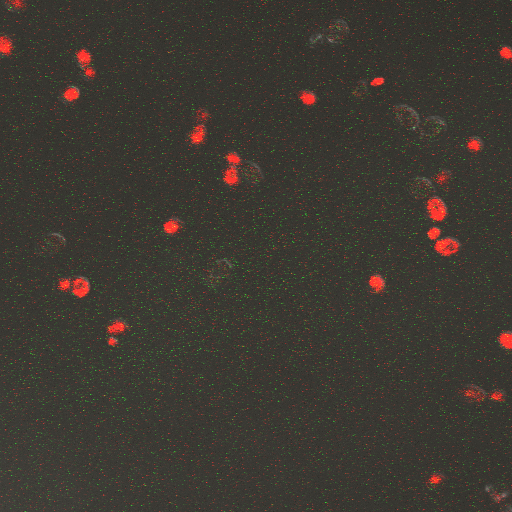
Representative Images: | Representative Images: | ||
| + | {| | ||
| + | |[[Image:CDRE_RFP_no_shock.jpg|200px|thumb|No electrostimulus on yeast without vesicular pumps]] | ||
| + | |[[Image:CDRE_RFP_2.jpg|200px|thumb|6 Volts electrostimulus on yeast without vesicular pumps]] | ||
| + | |[[Image:CDRE_RFP_3.jpg|200px|thumb|8 Volts electrostimulus on yeast without vesicular pumps]] | ||
| + | |[[Image:CDRE_RFP_1.jpg|200px|thumb|10 Volts electrostimulus on yeast without vesicular pumps]] | ||
| + | |} | ||
| + | |||
====Results==== | ====Results==== | ||
{| border="1" cellpadding="5" cellspacing="0" style="background: #ffffff;" | {| border="1" cellpadding="5" cellspacing="0" style="background: #ffffff;" | ||
| Line 108: | Line 93: | ||
|} | |} | ||
| - | ====Conclusions and Discussion | + | ====Conclusions and Discussion==== |
First, observe that the channels are inactive for the lowest stimulus durations. Some of these durations are on cellular diffusive timescales, so not enough calcium can enter the cells. Also, cells can quickly move to extrude the excess calcium. | First, observe that the channels are inactive for the lowest stimulus durations. Some of these durations are on cellular diffusive timescales, so not enough calcium can enter the cells. Also, cells can quickly move to extrude the excess calcium. | ||
| Line 121: | Line 106: | ||
''Name of S. cerevisiae strain:''Delta VCX1 Delta PMC1 W 303 with CDRE-RFP | ''Name of S. cerevisiae strain:''Delta VCX1 Delta PMC1 W 303 with CDRE-RFP | ||
| - | ====Observations | + | ====Observations==== |
| - | From the imaging of the shocked | + | From the imaging of the shocked yeast cells lacking vesicular calcium pumps we find that the cells start expressing RFP after 90 seconds of shocking. We saw expression in all the samples between 90 and 130 seconds with a definite trend of increase. The overall expression of RFP was pretty low, however, and only a few of the total cells expressed. It was also difficult to establish cytosol localization of RFP due to clumping of cells. We saw no expression of RFP in the 0 second shock trial. |
| - | From imaging the | + | From imaging the yeast samples with vesicular calcium pumps we found very high expression levels overall. There was constitutive expression in the negative control i.e. the 0 second shock trial, and the expression of RFP increased rapidly with increased shocking time, with maximum saturation at 50 seconds. After this it was not possible to visually distinguish weather there was any increase in expression levels. There was definite localization of RFP in the cytoplasm. In the samples with vesicular calcium pumps, most of the cells expressed RFP. Another observation made during imaging was that the cells with vesicular pumps were a lot healthier looking and bigger than the ones without. |
====Results==== | ====Results==== | ||
| - | [[Image:FSK2-1.jpeg]] | + | {| |
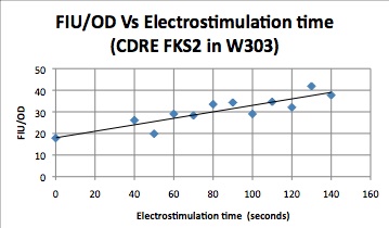
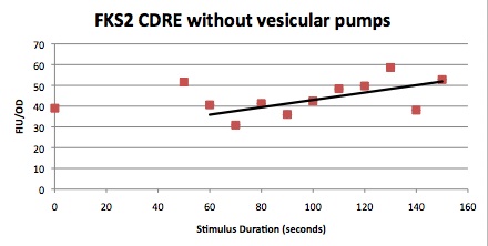
| + | |[[Image:FSK2-1.jpeg|frame|This graph shows the increasing linear relationship that electrostimulation time has with reporter gene expression. In this experiment, the promoter incorporated the CDRE from FKS2 and had vesicular calcium pumps present.]] | ||
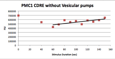
| + | |[[Image:PMC1-1.jpeg|frame|This graph shows the increasing linear relationship that electrostimulation time has with reporter gene expression. In this experiment, the promoter incorporated the CDRE from PMC1 and was null for vesicular calcium pumps.]] | ||
| + | |} | ||
{| | {| | ||
| - | |[[Image:Hone_in_0_Sec_KI.jpg|200px|thumb| | + | |[[Image:Hone_in_0_Sec_KI.jpg|200px|thumb|0 seconds of electrostimulus on yeast with vesicular pumps]] |
| - | |[[Image:Hone_in_60_Sec_KI.jpg|200px|thumb| | + | |[[Image:Hone_in_60_Sec_KI.jpg|200px|thumb|60 seconds of electrostimulus on yeast with vesicular pumps]] |
| - | |[[Image:Hone_in_90_Sec_KI.jpg|200px|thumb| | + | |[[Image:Hone_in_90_Sec_KI.jpg|200px|thumb|90 seconds of electrostimulus on yeast with vesicular pumps]] |
| - | |[[Image:Hone_in_110_Sec_KI.jpg|200px|thumb| | + | |[[Image:Hone_in_110_Sec_KI.jpg|200px|thumb|110 seconds of electrostimulus on yeast with vesicular pumps]] |
|} | |} | ||
{| | {| | ||
| - | |[[Image:Hone_in_60_Sec_KO.jpg|200px|thumb| | + | |[[Image:Hone_in_60_Sec_KO.jpg|200px|thumb|60 seconds of electrostimulus on yeast without vesicular pumps]] |
| - | |[[Image:Hone_in_80_Sec_KO.jpg|200px|thumb| | + | |[[Image:Hone_in_80_Sec_KO.jpg|200px|thumb|80 seconds of electrostimulus on yeast without vesicular pumps]] |
| - | |[[Image:Hone_in_90_Sec_KO.jpg|200px|thumb| | + | |[[Image:Hone_in_90_Sec_KO.jpg|200px|thumb|90 seconds of electrostimulus on yeast without vesicular pumps]] |
| - | |[[Image:Hone_in_110_Sec_KO.jpg|200px|thumb| | + | |[[Image:Hone_in_110_Sec_KO.jpg|200px|thumb|110 seconds of electrostimulus on yeast without vesicular pumps]] |
|- | |- | ||
| - | |[[Image:Hone_in_130_Sec_KO.jpg|200px|thumb| | + | |[[Image:Hone_in_130_Sec_KO.jpg|200px|thumb|130 seconds of electrostimulus on yeast without vesicular pumps]] |
|} | |} | ||
====Conclusions==== | ====Conclusions==== | ||
| - | From this experiment we can conclude that the | + | From this experiment we can conclude that the CDRE–RFP plasmid was successfully inserted into the PMC1, VCX1 yeast strain lacking calcium vacuoles. We can also establish that the activation region of the CDRE–RFP system is between 90 and 130 seconds of shocking, with a definite increase in expression levels with an increase in time shocked. We can also establish that there is no constitutive expression of CDRE–RFP from the fact that there is no RFP seen in the 0 second control. The overall expression of the system is weak however and it is only after 110 seconds that more than half of the cells in the frame start to express. We also observed that the cells lacking calcium pumps are smaller and less healthy looking than the cells with the pumps, which is probably because they are less able to deal with calcium shock induced by shocking and so more strained and unhealthy. |
| - | From the images of the | + | From the images of the vesicular pump lacking yeast we can see that there is significantly higher expression levels with constitutive expression. We also can see that the rate of increase in expression with time is much higher and the region where the CDRE gets activated is much earlier than with the yeast without the pumps. We theorize that the reason for this increased expression in yeast containing vesicular pumps could be because of a combination of two reasons. First, because they do not have PMC1 and VCX1 knocked out they have the ability to pump calcium out of the cytosol and into vacuoles making them more resistant to calcium shock and hence more healthy and better able to express the RFP. The other possible reason is that PMC1 and/or VCX1 may have feedback loops, and as PMC1 does have constitutive expression the vesicular pump containing cells may be having their RFP expression rates amplified by this effect. We believe that a combination of these two effects causes the increased expression rates. |
| - | ===Characterization Of CDRE-RFP system in wild type yeast and PMC1-YFP system in | + | ===Characterization Of CDRE-RFP system in wild type yeast and PMC1-YFP system in Vesicular Pump Negative Yeast Strain=== |
''Reason for doing the experiment:''To characterize the relationship between electrostimulation times and expression of florescent protein of the synthetic CDRE promoter sequence and the PMC1 promoter sequence. Also to demonstrate the effect of knocking out the PMC1 and VCX1 genes in yeast.<br> | ''Reason for doing the experiment:''To characterize the relationship between electrostimulation times and expression of florescent protein of the synthetic CDRE promoter sequence and the PMC1 promoter sequence. Also to demonstrate the effect of knocking out the PMC1 and VCX1 genes in yeast.<br> | ||
''Date:''10/7/10<br> | ''Date:''10/7/10<br> | ||
| Line 164: | Line 152: | ||
==Protocol== | ==Protocol== | ||
===Plasmid Extraction=== | ===Plasmid Extraction=== | ||
| - | ====Reagents | + | ====Reagents==== |
# '''Buffer P1 - Resuspension Buffer''' <br> 50mM Tris-Cl, pH 8.0, 10mM EDTA, 100ug/mL RNase A <br>Storage condition - 4oC after adding RNase A <br>Prep - Dissolve 6.06g Tris base, 3.72g EDTA-2H20 in 800mL dH20. Adjust the pH to 8.0 with HCl.<br>Adjust the volume to 1 liter with dH2O. Add 100mg RNase A per liter of P1. | # '''Buffer P1 - Resuspension Buffer''' <br> 50mM Tris-Cl, pH 8.0, 10mM EDTA, 100ug/mL RNase A <br>Storage condition - 4oC after adding RNase A <br>Prep - Dissolve 6.06g Tris base, 3.72g EDTA-2H20 in 800mL dH20. Adjust the pH to 8.0 with HCl.<br>Adjust the volume to 1 liter with dH2O. Add 100mg RNase A per liter of P1. | ||
# '''Buffer P2 - Lysis Buffer'''<br>200mM NaOH, 1% SDS<br>Storage condition - RT<br>Dissolve 8.09g of NaOH pellets in 950mL dH2O, 50mL 20% SDS solution. <br>The final volume should be 1 liter. | # '''Buffer P2 - Lysis Buffer'''<br>200mM NaOH, 1% SDS<br>Storage condition - RT<br>Dissolve 8.09g of NaOH pellets in 950mL dH2O, 50mL 20% SDS solution. <br>The final volume should be 1 liter. | ||
| Line 170: | Line 158: | ||
# '''PB Buffer - Binding Buffer'''<br>Composition Unknown (Proprietary)<br>Storage condition - RT | # '''PB Buffer - Binding Buffer'''<br>Composition Unknown (Proprietary)<br>Storage condition - RT | ||
# '''Buffer PE - Wash Buffer'''<br>Composition unknown<br>Storage condition - RT | # '''Buffer PE - Wash Buffer'''<br>Composition unknown<br>Storage condition - RT | ||
| - | ====Protocol | + | |
| + | ====Protocol==== | ||
# Innoculate 3-4 mL of the E. coli cells in glass tubes with the right selection resistance in LB (Luria Bertani) medium. | # Innoculate 3-4 mL of the E. coli cells in glass tubes with the right selection resistance in LB (Luria Bertani) medium. | ||
# Transfer solution to a 2 mL Eppendorf tube and spin down at max speed (~13,000 rpm) for 30 seconds. | # Transfer solution to a 2 mL Eppendorf tube and spin down at max speed (~13,000 rpm) for 30 seconds. | ||
| Line 188: | Line 177: | ||
# Confirm size with gel electrophoresis with 1% agarose gel and appropriate DNA Ladder. (Remember circular plasmids can become supercoiled and produce smaller apparent sizes on the gel) | # Confirm size with gel electrophoresis with 1% agarose gel and appropriate DNA Ladder. (Remember circular plasmids can become supercoiled and produce smaller apparent sizes on the gel) | ||
# Use Nanodrop™ to confirm DNA concentration. | # Use Nanodrop™ to confirm DNA concentration. | ||
| + | |||
===Yeast Transformation=== | ===Yeast Transformation=== | ||
To transform a desired plasmid into a host yeast cell.<br>Date: 8/25/10 Used to transform ref-GFP | To transform a desired plasmid into a host yeast cell.<br>Date: 8/25/10 Used to transform ref-GFP | ||
| - | ====Reagents | + | ====Reagents==== |
# '''PEG-TE LiOAc'''<br>10 mL 10x TE <br>10 mL 1 M LiOAc <br>80 mL 50% PEG (3350 mw)<br>Mix with stir bar, filter sterilize, store at 4 °C | # '''PEG-TE LiOAc'''<br>10 mL 10x TE <br>10 mL 1 M LiOAc <br>80 mL 50% PEG (3350 mw)<br>Mix with stir bar, filter sterilize, store at 4 °C | ||
# '''TE-LiOAc'''<br>10 mL 10x TE<br>10 mL 1 M LiOAc<br>80 mL H<sub>2</sub>O<br> | # '''TE-LiOAc'''<br>10 mL 10x TE<br>10 mL 1 M LiOAc<br>80 mL H<sub>2</sub>O<br> | ||
| Line 215: | Line 205: | ||
====Protocol==== | ====Protocol==== | ||
| - | A 96 well plate was set up with 2 rows of PMC1 and VCX1 | + | A 96 well plate was set up with 2 rows of PMC1 and VCX1 vacuole pump lacking yeast cells, with the CDRE–RPF plasmid in them. Two rows below that were filled with yeast cells with their pumps intact and the CDRE–RFP plasmid inserted in it. |
We also set aside 8 wells at the bottom as cleaning wells and filled them with ethanol. | We also set aside 8 wells at the bottom as cleaning wells and filled them with ethanol. | ||
| Line 230: | Line 220: | ||
====Procedure==== | ====Procedure==== | ||
| - | A 96 well plate was set up with 2 rows of PMC1 and VCX1 | + | A 96 well plate was set up with 2 rows of PMC1 and VCX1 vacuole pump lacking yeast cells, with the CDRE – RPF plasmid in them. Two rows below that were filled with yeast cells with their pumps intact and the CDRE – RFP plasmid inserted in it. We also set aside 8 wells at the bottom as cleaning wells and filled them with ethanol. |
The shocking of the cells was carried out using a coaxial electrode system, consisting of 8 sets of gold plated electrodes that fit into the 8 wells of a 96 well plate. An oscilloscope was connected in parallel to the electrode. The shocking was done at 8 V and at 20HZ frequency. The pulses were all sinusoidal. | The shocking of the cells was carried out using a coaxial electrode system, consisting of 8 sets of gold plated electrodes that fit into the 8 wells of a 96 well plate. An oscilloscope was connected in parallel to the electrode. The shocking was done at 8 V and at 20HZ frequency. The pulses were all sinusoidal. | ||
| Line 239: | Line 229: | ||
After re suspending any settled cells in the well being tested, 20ul of the cell solution was pipetted onto a slide and a cover slip was placed over it. Some oil was spread on the cover slip and the cells were imaged. At least 2 pictures were taken from each sample. | After re suspending any settled cells in the well being tested, 20ul of the cell solution was pipetted onto a slide and a cover slip was placed over it. Some oil was spread on the cover slip and the cells were imaged. At least 2 pictures were taken from each sample. | ||
| - | ===Characterization Of CDRE-RFP | + | ===Characterization Of CDRE-RFP System in Wild Type Yeast and PMC1-YFP system in Yeast Strain Lacking Vesicular Calcium Pumps=== |
====Procedure==== | ====Procedure==== | ||
| - | A 96 well plate was set up with 1 rows of W303 yeast cells, with the CDRE – RPF plasmid in them. One row below that were filled with yeast cells with PMC1 and VCX1 | + | A 96 well plate was set up with 1 rows of W303 yeast cells, with the CDRE – RPF plasmid in them. One row below that were filled with yeast cells with PMC1 and VCX1 without their calcium vacuole pumps the PMC1 - YFP plasmid inserted in it. |
The shocking of the cells was carried out using a coaxial electrode system, consisting of 8 sets of gold plated electrodes that fit into the 8 wells of a 96 well plate. An oscilloscope was connected in parallel to the electrode. The shocking was done at 8 V and at 20HZ frequency. The pulses were all sinusoidal. | The shocking of the cells was carried out using a coaxial electrode system, consisting of 8 sets of gold plated electrodes that fit into the 8 wells of a 96 well plate. An oscilloscope was connected in parallel to the electrode. The shocking was done at 8 V and at 20HZ frequency. The pulses were all sinusoidal. | ||
| Line 279: | Line 269: | ||
|140||37.71948052||360177.9279 | |140||37.71948052||360177.9279 | ||
|} | |} | ||
| - | ===Characterization Of CDRE-RFP and PMC1-YFP system in wild type yeast and | + | |
| + | ===Characterization Of CDRE-RFP in wild type yeast and Yeast Strain Vesicular Calcium Pump Negative and the PMC1-YFP system in wild type yeast and Vesicular Negative Yeast=== | ||
====Procedure==== | ====Procedure==== | ||
| Line 293: | Line 284: | ||
These cells were then put in a plate reader that measured OD, as a measure of cell growth in the samples over the expression period of 8 hours. After this the plate was put in a plate florometer and RFP and YFP intensities were measured. The growth and expression was so measured at one hour intervals from three hours later to 8 hours later. The following data was collected. | These cells were then put in a plate reader that measured OD, as a measure of cell growth in the samples over the expression period of 8 hours. After this the plate was put in a plate florometer and RFP and YFP intensities were measured. The growth and expression was so measured at one hour intervals from three hours later to 8 hours later. The following data was collected. | ||
| + | |||
===Plasmid Extraction=== | ===Plasmid Extraction=== | ||
| - | ====Reagents | + | ====Reagents==== |
# '''Buffer P1 - Resuspension Buffer''' <br> 50mM Tris-Cl, pH 8.0, 10mM EDTA, 100ug/mL RNase A <br>Storage condition - 4oC after adding RNase A <br>Prep - Dissolve 6.06g Tris base, 3.72g EDTA-2H20 in 800mL dH20. Adjust the pH to 8.0 with HCl.<br>Adjust the volume to 1 liter with dH2O. Add 100mg RNase A per liter of P1. | # '''Buffer P1 - Resuspension Buffer''' <br> 50mM Tris-Cl, pH 8.0, 10mM EDTA, 100ug/mL RNase A <br>Storage condition - 4oC after adding RNase A <br>Prep - Dissolve 6.06g Tris base, 3.72g EDTA-2H20 in 800mL dH20. Adjust the pH to 8.0 with HCl.<br>Adjust the volume to 1 liter with dH2O. Add 100mg RNase A per liter of P1. | ||
# '''Buffer P2 - Lysis Buffer'''<br>200mM NaOH, 1% SDS<br>Storage condition - RT<br>Dissolve 8.09g of NaOH pellets in 950mL dH2O, 50mL 20% SDS solution. <br>The final volume should be 1 liter. | # '''Buffer P2 - Lysis Buffer'''<br>200mM NaOH, 1% SDS<br>Storage condition - RT<br>Dissolve 8.09g of NaOH pellets in 950mL dH2O, 50mL 20% SDS solution. <br>The final volume should be 1 liter. | ||
| Line 300: | Line 292: | ||
# '''PB Buffer - Binding Buffer'''<br>Composition Unknown (Proprietary)<br>Storage condition - RT | # '''PB Buffer - Binding Buffer'''<br>Composition Unknown (Proprietary)<br>Storage condition - RT | ||
# '''Buffer PE - Wash Buffer'''<br>Composition unknown<br>Storage condition - RT | # '''Buffer PE - Wash Buffer'''<br>Composition unknown<br>Storage condition - RT | ||
| - | ====Protocol | + | ====Protocol==== |
# Innoculate 3-4 mL of the E. coli cells in glass tubes with the right selection resistance in LB (Luria Bertani) medium. | # Innoculate 3-4 mL of the E. coli cells in glass tubes with the right selection resistance in LB (Luria Bertani) medium. | ||
# Transfer solution to a 2 mL Eppendorf tube and spin down at max speed (~13,000 rpm) for 30 seconds. | # Transfer solution to a 2 mL Eppendorf tube and spin down at max speed (~13,000 rpm) for 30 seconds. | ||
| Line 320: | Line 312: | ||
===Yeast Transformation=== | ===Yeast Transformation=== | ||
To transform a desired plasmid into a host yeast cell.<br>Date: 8/25/10 Used to transform ref-GFP | To transform a desired plasmid into a host yeast cell.<br>Date: 8/25/10 Used to transform ref-GFP | ||
| - | ====Reagents | + | ====Reagents==== |
# '''PEG-TE LiOAc'''<br>10 mL 10x TE <br>10 mL 1 M LiOAc <br>80 mL 50% PEG (3350 mw)<br>Mix with stir bar, filter sterilize, store at 4 °C | # '''PEG-TE LiOAc'''<br>10 mL 10x TE <br>10 mL 1 M LiOAc <br>80 mL 50% PEG (3350 mw)<br>Mix with stir bar, filter sterilize, store at 4 °C | ||
# '''TE-LiOAc'''<br>10 mL 10x TE<br>10 mL 1 M LiOAc<br>80 mL H<sub>2</sub>O<br> | # '''TE-LiOAc'''<br>10 mL 10x TE<br>10 mL 1 M LiOAc<br>80 mL H<sub>2</sub>O<br> | ||
| Line 348: | Line 340: | ||
# '''Solution III (KOAc solution):'''<br>to make 100 mL; add:<br>60 mL 5 M KOAc<br>11.5 mL glacial acetic acid<br>28.5 mL diH2O<br>keep refrigerated<br>pH should be around 6.0<br> | # '''Solution III (KOAc solution):'''<br>to make 100 mL; add:<br>60 mL 5 M KOAc<br>11.5 mL glacial acetic acid<br>28.5 mL diH2O<br>keep refrigerated<br>pH should be around 6.0<br> | ||
| - | ====Protocol | + | ====Protocol==== |
# Innoculate 5 mL of sterile growth medium containing appropriate antibiotic with a single bacterial colony. Incubate at 37 C in the incubator shaker. Allow to grow until a stationary phase is reached (overnight is ideal). | # Innoculate 5 mL of sterile growth medium containing appropriate antibiotic with a single bacterial colony. Incubate at 37 C in the incubator shaker. Allow to grow until a stationary phase is reached (overnight is ideal). | ||
# Transter 2 x 750 µL aliquots from each overnight culture into a labeled eppendorf tube. Pellet the cells by spinning for 3 to 5 minutes in the microfuge at maximum speed. | # Transter 2 x 750 µL aliquots from each overnight culture into a labeled eppendorf tube. Pellet the cells by spinning for 3 to 5 minutes in the microfuge at maximum speed. | ||
| Line 369: | Line 361: | ||
===SC Media=== | ===SC Media=== | ||
| - | ====Reagents | + | ====Reagents==== |
{| border="1" cellpadding="5" cellspacing="0" style="background: #ffffff;" | {| border="1" cellpadding="5" cellspacing="0" style="background: #ffffff;" | ||
|+Start with 600 mL of autoclaved H2O and add the following: | |+Start with 600 mL of autoclaved H2O and add the following: | ||
Latest revision as of 03:57, 28 October 2010
Experiments
Crz1-GFP Experiment
Reason for doing the experiment: To establish whether shocking the cells induces calcium influx leading to CRZ1 nuclear localization.
Date: 21/7/10
Location: Imaging Center
Name of S. cerevisiae strain: Delta VCX1 Delta PMC1 with Crz1 tagged with GFP
Representative images:
Conclusions and discussion
From this experiment it is clear that there is a calcium influx into the cell on application of a voltage across the cell membrane. We have also established that there is a significant influx of Crz1 into the nucleus associated with this calcium influx as we expected. We hypothesis that the reason we saw Crz1 nuclear localisation only in cells very close to the live electrode because the voltage provided by the function generator was too low to reach across the gap, and so a hypothetical ground gets formed near the live electrode. Another reason may be that as our device has the electrodes at a large distance from each other, comparable x.
CDRE Optimization Experiment
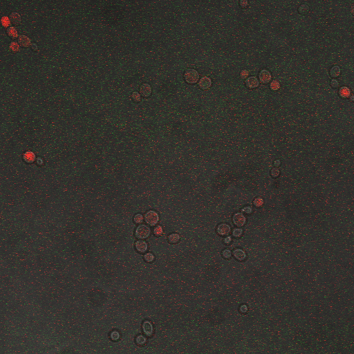
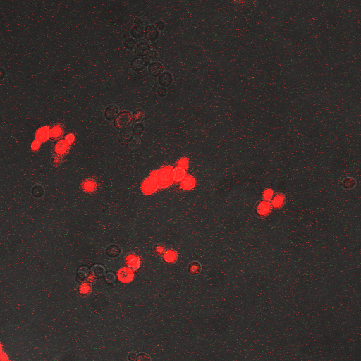
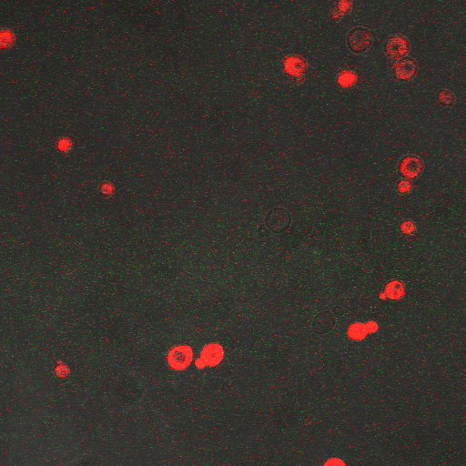
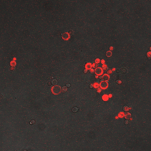
Reason for doing the experiment:To find an optimum voltage amplitude and shocking time for yeast containing the CDRE-RFP plasmid.
Date:10/7/10
Location: Imaging Center
Name of S. cerevisiae strain:Delta VCX1 Delta PMC1 W303 with CDRE-RFP
Representative Images:
Results
| 2s | 5s | 10s | 20s | 40s | 80s | |
|---|---|---|---|---|---|---|
| 10V | None | None | None | None | None | N/A |
| 8V | None | None | None | None | High | High |
| 6V | None | None | None | None | Moderate | High |
| 4V | None | None | None | None | Low | Low |
Conclusions and Discussion
First, observe that the channels are inactive for the lowest stimulus durations. Some of these durations are on cellular diffusive timescales, so not enough calcium can enter the cells. Also, cells can quickly move to extrude the excess calcium.
Second, consider the channel mechanics. Calcium channel gates alternate between open and closed states based on first order kinetics, where the rate constants are exponential functions of voltage. The open probability curve increases rather steeply, made even steeper since having n channels raises the probability curve to the nth power. This curve was found to rise rapidly between 4V and 8V to a maximum around 8V. At 10V, however, shorter stimulus durations are insufficient to trigger calcineurin, but longer durations kill the cells.
From our experiments we found that there was significant expression of RFP after 40 seconds of shocking. We can also establish that a ten volt voltage amplitude kills most of the cells, which from literature (REFERENCE) is probably due to membrane disruption. The maximum expression we can get without damaging the cells is with an 8V shocking voltage amplitude.
CDRE hone in Experiment
Reason for doing the experiment:To hone in on the CDRE systems region of activation with respect to time of shocking. Also to compare yeast without PMC1 and VCX1 knocked out versus yeast with it knocked out to determine effect of the knockout on the CDRE systems expression levels.
Date:10/7/10
Location:Imaging Center
Name of S. cerevisiae strain:Delta VCX1 Delta PMC1 W 303 with CDRE-RFP
Observations
From the imaging of the shocked yeast cells lacking vesicular calcium pumps we find that the cells start expressing RFP after 90 seconds of shocking. We saw expression in all the samples between 90 and 130 seconds with a definite trend of increase. The overall expression of RFP was pretty low, however, and only a few of the total cells expressed. It was also difficult to establish cytosol localization of RFP due to clumping of cells. We saw no expression of RFP in the 0 second shock trial.
From imaging the yeast samples with vesicular calcium pumps we found very high expression levels overall. There was constitutive expression in the negative control i.e. the 0 second shock trial, and the expression of RFP increased rapidly with increased shocking time, with maximum saturation at 50 seconds. After this it was not possible to visually distinguish weather there was any increase in expression levels. There was definite localization of RFP in the cytoplasm. In the samples with vesicular calcium pumps, most of the cells expressed RFP. Another observation made during imaging was that the cells with vesicular pumps were a lot healthier looking and bigger than the ones without.
Results
Conclusions
From this experiment we can conclude that the CDRE–RFP plasmid was successfully inserted into the PMC1, VCX1 yeast strain lacking calcium vacuoles. We can also establish that the activation region of the CDRE–RFP system is between 90 and 130 seconds of shocking, with a definite increase in expression levels with an increase in time shocked. We can also establish that there is no constitutive expression of CDRE–RFP from the fact that there is no RFP seen in the 0 second control. The overall expression of the system is weak however and it is only after 110 seconds that more than half of the cells in the frame start to express. We also observed that the cells lacking calcium pumps are smaller and less healthy looking than the cells with the pumps, which is probably because they are less able to deal with calcium shock induced by shocking and so more strained and unhealthy.
From the images of the vesicular pump lacking yeast we can see that there is significantly higher expression levels with constitutive expression. We also can see that the rate of increase in expression with time is much higher and the region where the CDRE gets activated is much earlier than with the yeast without the pumps. We theorize that the reason for this increased expression in yeast containing vesicular pumps could be because of a combination of two reasons. First, because they do not have PMC1 and VCX1 knocked out they have the ability to pump calcium out of the cytosol and into vacuoles making them more resistant to calcium shock and hence more healthy and better able to express the RFP. The other possible reason is that PMC1 and/or VCX1 may have feedback loops, and as PMC1 does have constitutive expression the vesicular pump containing cells may be having their RFP expression rates amplified by this effect. We believe that a combination of these two effects causes the increased expression rates.
Characterization Of CDRE-RFP system in wild type yeast and PMC1-YFP system in Vesicular Pump Negative Yeast Strain
Reason for doing the experiment:To characterize the relationship between electrostimulation times and expression of florescent protein of the synthetic CDRE promoter sequence and the PMC1 promoter sequence. Also to demonstrate the effect of knocking out the PMC1 and VCX1 genes in yeast.
Date:10/7/10
Location:Ostermeier Complex
Name of S. cerevisiae strain:W303 with CDRE-RFP, Delta VCX1 Delta PMC1 W303 with PMC-YFP
Results
Protocol
Plasmid Extraction
Reagents
- Buffer P1 - Resuspension Buffer
50mM Tris-Cl, pH 8.0, 10mM EDTA, 100ug/mL RNase A
Storage condition - 4oC after adding RNase A
Prep - Dissolve 6.06g Tris base, 3.72g EDTA-2H20 in 800mL dH20. Adjust the pH to 8.0 with HCl.
Adjust the volume to 1 liter with dH2O. Add 100mg RNase A per liter of P1. - Buffer P2 - Lysis Buffer
200mM NaOH, 1% SDS
Storage condition - RT
Dissolve 8.09g of NaOH pellets in 950mL dH2O, 50mL 20% SDS solution.
The final volume should be 1 liter. - Buffer N3 - Neutralization Buffer for spin columns.
Composition unknown
Storage condition - RT - PB Buffer - Binding Buffer
Composition Unknown (Proprietary)
Storage condition - RT - Buffer PE - Wash Buffer
Composition unknown
Storage condition - RT
Protocol
- Innoculate 3-4 mL of the E. coli cells in glass tubes with the right selection resistance in LB (Luria Bertani) medium.
- Transfer solution to a 2 mL Eppendorf tube and spin down at max speed (~13,000 rpm) for 30 seconds.
- Pour out LB medium and repeat until all of the solution from the innoculation tube is pelleted at the bottom of the Eppendorf tube. Each spin down after the first requires one full minute.
- Re-suspend the pelleted E. coli in 250 µL Buffer P1 and transfer solution to micro-centrifuge tube provided by the Qiaprep Kit. (This can be the same tube as the 2 mL Eppendorf tube) This step requires a strong vortex in order to fully re-suspend the pelleted cells. May require 3-4 minutes of continuous agitation.
- Add 250 µL of Buffer P2 and mix gently by inverting the tube 4-6 times. Be very gentle! Shear stresses can ruin the experiment after the lysis of cells from P2 Buffer.
- Add 350 µL of Buffer N3 and mix immediately and thoroughly by inverting the tube 4-6 times.
- Spin down at max speed for 10 minutes. A white pellet near the bottom and side of the walls will form.
- Extract the supernatant and add 500 µL of PB buffer. Place mixture into the Qiaprep spin column.
- Centrifuge mixture for 1 minute, max speed.
- Remove liquid at bottom.
- Add 750 µL of PE Buffer to Qiaprep spin column.
- Centrifuge mixture for 1 minute, max speed.
- Remove liquid at bottom and centrifuge again for 1 minute at max speed to remove more of the PE buffer.
- Transfer Qiaprep spin column to sterile Eppendorf tube and add 50 µL of dH2O and let the spin column equilibrate for 10 minutes with the dH2O.
- Spin down column for 1 minute, max speed.
- Confirm size with gel electrophoresis with 1% agarose gel and appropriate DNA Ladder. (Remember circular plasmids can become supercoiled and produce smaller apparent sizes on the gel)
- Use Nanodrop™ to confirm DNA concentration.
Yeast Transformation
To transform a desired plasmid into a host yeast cell.
Date: 8/25/10 Used to transform ref-GFP
Reagents
- PEG-TE LiOAc
10 mL 10x TE
10 mL 1 M LiOAc
80 mL 50% PEG (3350 mw)
Mix with stir bar, filter sterilize, store at 4 °C - TE-LiOAc
10 mL 10x TE
10 mL 1 M LiOAc
80 mL H2O
- 10x TE
70 mL Tris Base (1M)
30 mL 1M Tris-Cl
20 mL 0.5 M EDTA: pH 8.0
880 mL diH2O
Autoclave: 45 min - SsDNA-(Stratagene #201190-81)
Sonicated Salmon Sperm DNA
ssDNA: 10mg/mL; 1 mL vial
Store at -20°C - 1 M Lithium Acetate-(LiOAc: Sigm L-6883)
102.0 g LiOAc
Bring to 1L diH2O
Autoclave 45 min. - 50% PEG-3350-(Sigma P-4338)
250g PEG to 250 mL warm diH2O
Bring to 500 mL diH2O
Filter Sterilize
Protocol
- Grow yeast cells to log phase in 5 mL YPD medium overnight @ 30 degrees.
- Harvest (5 min, 2000 rpm);aspirate supernatant (sterile tip).
- Wash cell pellet 1X with 1mL TE-LiOAc; transfer to eppendorph tubes.
- Resuspend in 100 µL of TE-LiOAc.
- Add (mix after each):
- 2.5µL Fresh Boiled ssDNA (10 mg/mL)
- 1µL Mini-Prep Plasmid DNA
- 800µL PEG - TE -LiOAc
- Incubate @ 30 C; 30 min. Heat Shock 42 C; ~20 minutes.
- Harvest cells (30 sec,~14000 rpm), aspirate supernatant.
- Wash pellet 1x with 1 mL of YPD.
- Resuspend in 100-250 µL of YPD. Plate onto YPD. Incubate plates 2 days at 30 C.
(Optional: plate onto YPD for 1 day and then replica-plate onto selective medium)
CDRE Optimization
Protocol
A 96 well plate was set up with 2 rows of PMC1 and VCX1 vacuole pump lacking yeast cells, with the CDRE–RPF plasmid in them. Two rows below that were filled with yeast cells with their pumps intact and the CDRE–RFP plasmid inserted in it. We also set aside 8 wells at the bottom as cleaning wells and filled them with ethanol.
The shocking of the cells was carried out using a coaxial electrode system, consisting of 8 sets of gold plated electrodes that fit into the 8 wells of a 96 well plate. An oscilloscope was connected in parallel to the electrode. The shocking was done at 8 V and at 20HZ frequency. The pulses were all sinusoidal.
The cells were shocked for increasing time intervals from 30 seconds to 130 seconds in ten second increments. There was also a 0 second control for every row of cells. Between each shocking the electrodes were first repeatedly dipped in the ethanol wells to clean them and then dipped in a water bath to remove any residual ethanol, then dried using Kim wipes.
After shocking the 96 well plate was put in a shaker at 37C for 8 hours. They were then imaged using a Meta 510 confocal microscope. A 60X oil objective was used and Rodamine and FIT-C filters were applied.
After re suspending any settled cells in the well being tested, 20ul of the cell solution was pipetted onto a slide and a cover slip was placed over it. Some oil was spread on the cover slip and the cells were imaged. At least 2 pictures were taken from each sample.
CDRE Hone in
Procedure
A 96 well plate was set up with 2 rows of PMC1 and VCX1 vacuole pump lacking yeast cells, with the CDRE – RPF plasmid in them. Two rows below that were filled with yeast cells with their pumps intact and the CDRE – RFP plasmid inserted in it. We also set aside 8 wells at the bottom as cleaning wells and filled them with ethanol.
The shocking of the cells was carried out using a coaxial electrode system, consisting of 8 sets of gold plated electrodes that fit into the 8 wells of a 96 well plate. An oscilloscope was connected in parallel to the electrode. The shocking was done at 8 V and at 20HZ frequency. The pulses were all sinusoidal.
The cells were shocked for increasing time intervals from 30 seconds to 130 seconds in ten second increments. There was also a 0 second control for every row of cells. Between each shocking the electrodes were first repeatedly dipped in the ethanol wells to clean them and then dipped in a water bath to remove any residual ethanol, then dried using Kim wipes. After shocking the 96 well plate was put in a shaker at 37C for 8 hours. They were then imaged using a Meta 510 confocal microscope. A 60X oil objective was used and Rodamine and FIT-C filters were applied.
After re suspending any settled cells in the well being tested, 20ul of the cell solution was pipetted onto a slide and a cover slip was placed over it. Some oil was spread on the cover slip and the cells were imaged. At least 2 pictures were taken from each sample.
Characterization Of CDRE-RFP System in Wild Type Yeast and PMC1-YFP system in Yeast Strain Lacking Vesicular Calcium Pumps
Procedure
A 96 well plate was set up with 1 rows of W303 yeast cells, with the CDRE – RPF plasmid in them. One row below that were filled with yeast cells with PMC1 and VCX1 without their calcium vacuole pumps the PMC1 - YFP plasmid inserted in it.
The shocking of the cells was carried out using a coaxial electrode system, consisting of 8 sets of gold plated electrodes that fit into the 8 wells of a 96 well plate. An oscilloscope was connected in parallel to the electrode. The shocking was done at 8 V and at 20HZ frequency. The pulses were all sinusoidal.
The cells were shocked for increasing time intervals from 40 seconds to 150 seconds in ten second increments. There was also a 0 second control for every row of cells. Between each shocking the electrodes were first repeatedly dipped in the ethanol wells to clean them and then dipped in a water bath to remove any residual ethanol, then dried using Kim wipes. After shocking the 96 well plate was put in a shaker at 37C for 8 hours.
These cells were then put in a plate reader that measured OD, as a measure of cell growth in the samples over the expression period of 8 hours. After this the plate was put in a plate florometer and RFP and YFP intensities were measured. The following data was collected.
| Time/FIU/OD | CDRE | PMC1 |
|---|---|---|
| 0 | 17.85119048 | 263121.1632 |
| 40 | 26.10337553 | 338282.2967 |
| 50 | 19.86680328 | 293471.7742 |
| 60 | 29.04337349 | 456021.0843 |
| 70 | 28.32403433 | 484804.1237 |
| 80 | 33.50247525 | 505993.6102 |
| 90 | 34.32098765 | 544573.5294 |
| 100 | 29.03455724 | 311173.5358 |
| 110 | 34.65552699 | 262445.7237 |
| 120 | 32.08673469 | 506424.9201 |
| 130 | 41.87246377 | 485111.8881 |
| 140 | 37.71948052 | 360177.9279 |
Characterization Of CDRE-RFP in wild type yeast and Yeast Strain Vesicular Calcium Pump Negative and the PMC1-YFP system in wild type yeast and Vesicular Negative Yeast
Procedure
Two 96 well plates were set up with one having 4 rows of W303 yeast cells, with the CDRE – RPF plasmid in them. 4 rows below them were filled with yeast cells with PMC1 and VCX1 knocked out and the CDRE-RFP plasmid inserted in them.
The other has 4 rows of W303 yeast cells, with the CDRE – RPF plasmid in them. 4 rows below them were filled with yeast cells with PMC1 and VCX1 knocked out and the CDRE-RFP plasmid inserted in them.
The shocking of the cells was carried out using a coaxial electrode system, consisting of 8 sets of gold plated electrodes that fit into the 8 wells of a 96 well plate. An oscilloscope was connected in parallel to the electrode. The shocking was done at 8 V and at 20HZ frequency. The pulses were all sinusoidal.
The cells were shocked for increasing time intervals from 40 seconds to 150 seconds in ten second increments. There was also a 0 second control for every row of cells. Between each shocking the electrodes were first repeatedly dipped in the ethanol wells to clean them and then dipped in a water bath to remove any residual ethanol, then dried using Kim wipes. After shocking the 96 well plate were allowed to grow at room temperature.
These cells were then put in a plate reader that measured OD, as a measure of cell growth in the samples over the expression period of 8 hours. After this the plate was put in a plate florometer and RFP and YFP intensities were measured. The growth and expression was so measured at one hour intervals from three hours later to 8 hours later. The following data was collected.
Plasmid Extraction
Reagents
- Buffer P1 - Resuspension Buffer
50mM Tris-Cl, pH 8.0, 10mM EDTA, 100ug/mL RNase A
Storage condition - 4oC after adding RNase A
Prep - Dissolve 6.06g Tris base, 3.72g EDTA-2H20 in 800mL dH20. Adjust the pH to 8.0 with HCl.
Adjust the volume to 1 liter with dH2O. Add 100mg RNase A per liter of P1. - Buffer P2 - Lysis Buffer
200mM NaOH, 1% SDS
Storage condition - RT
Dissolve 8.09g of NaOH pellets in 950mL dH2O, 50mL 20% SDS solution.
The final volume should be 1 liter. - Buffer N3 - Neutralization Buffer for spin columns.
Composition unknown
Storage condition - RT - PB Buffer - Binding Buffer
Composition Unknown (Proprietary)
Storage condition - RT - Buffer PE - Wash Buffer
Composition unknown
Storage condition - RT
Protocol
- Innoculate 3-4 mL of the E. coli cells in glass tubes with the right selection resistance in LB (Luria Bertani) medium.
- Transfer solution to a 2 mL Eppendorf tube and spin down at max speed (~13,000 rpm) for 30 seconds.
- Pour out LB medium and repeat until all of the solution from the innoculation tube is pelleted at the bottom of the Eppendorf tube. Each spin down after the first requires one full minute.
- Re-suspend the pelleted E. coli in 250 µL Buffer P1 and transfer solution to micro-centrifuge tube provided by the Qiaprep Kit. (This can be the same tube as the 2 mL Eppendorf tube) This step requires a strong vortex in order to fully re-suspend the pelleted cells. May require 3-4 minutes of continuous agitation.
- Add 250 µL of Buffer P2 and mix gently by inverting the tube 4-6 times. Be very gentle! Shear stresses can ruin the experiment after the lysis of cells from P2 Buffer.
- Add 350 µL of Buffer N3 and mix immediately and thoroughly by inverting the tube 4-6 times.
- Spin down at max speed for 10 minutes. A white pellet near the bottom and side of the walls will form.
- Extract the supernatant and add 500 µL of PB buffer. Place mixture into the Qiaprep spin column.
- Centrifuge mixture for 1 minute, max speed.
- Remove liquid at bottom.
- Add 750 µL of PE Buffer to Qiaprep spin column.
- Centrifuge mixture for 1 minute, max speed.
- Remove liquid at bottom and centrifuge again for 1 minute at max speed to remove more of the PE buffer.
- Transfer Qiaprep spin column to sterile Eppendorf tube and add 50 µL of dH2O and let the spin column equilibrate for 10 minutes with the dH2O.
- Spin down column for 1 minute, max speed.
- Confirm size with gel electrophoresis with 1% agarose gel and appropriate DNA Ladder. (Remember circular plasmids can become supercoiled and produce smaller apparent sizes on the gel)
- Use Nanodrop™ to confirm DNA concentration.
Yeast Transformation
To transform a desired plasmid into a host yeast cell.
Date: 8/25/10 Used to transform ref-GFP
Reagents
- PEG-TE LiOAc
10 mL 10x TE
10 mL 1 M LiOAc
80 mL 50% PEG (3350 mw)
Mix with stir bar, filter sterilize, store at 4 °C - TE-LiOAc
10 mL 10x TE
10 mL 1 M LiOAc
80 mL H2O
- 10x TE
70 mL Tris Base (1M)
30 mL 1M Tris-Cl
20 mL 0.5 M EDTA: pH 8.0
880 mL diH2O
Autoclave: 45 min - SsDNA-(Stratagene #201190-81)
Sonicated Salmon Sperm DNA
ssDNA: 10mg/mL; 1 mL vial
Store at -20°C - 1 M Lithium Acetate-(LiOAc: Sigm L-6883)
102.0 g LiOAc
Bring to 1L diH2O
Autoclave 45 min. - 50% PEG-3350-(Sigma P-4338)
250g PEG to 250 mL warm diH2O
Bring to 500 mL diH2O
Filter Sterilize
Protocol
- Grow yeast cells to log phase in 5 mL YPD medium overnight @ 30 degrees.
- Harvest (5 min, 2000 rpm);aspirate supernatant (sterile tip).
- Wash cell pellet 1X with 1mL TE-LiOAc; transfer to eppendorph tubes.
- Resuspend in 100 µL of TE-LiOAc.
- Add (mix after each):
- 2.5µL Fresh Boiled ssDNA (10 mg/mL)
- 1µL Mini-Prep Plasmid DNA
- 800µL PEG - TE -LiOAc
- Incubate @ 30 C; 30 min. Heat Shock 42 C; ~20 minutes.
- Harvest cells (30 sec,~14000 rpm), aspirate supernatant.
- Wash pellet 1x with 1 mL of YPD.
- Resuspend in 100-250 µL of YPD. Plate onto YPD. Incubate plates 2 days at 30 C.
(Optional: plate onto YPD for 1 day and then replica-plate onto selective medium)
Plasmid Mini-Prep
Reagents
- Solutions 1 (Glucose/Tris/EDTA Solution):
2.3 mL 40% Glucose (50 mM Glucose)
2.5 mL Tris-Cl (25 mM Tris-Cl pH 8.0)
2 mL EDTA .5M (10 mM EDTA)
Bring to 100 mL with diH2O
keep refrigerated
- Solution II (NaOH/ SDS solution):
Mix (in order):
Make 10 mL fresh each time:
7.5 mL diH20
2 mL of 1N NaOH
0.5 mL of 20% SDS
Adjust the volume to 10 mL with diH2O after both SDS and NaOH have been added
- Solution III (KOAc solution):
to make 100 mL; add:
60 mL 5 M KOAc
11.5 mL glacial acetic acid
28.5 mL diH2O
keep refrigerated
pH should be around 6.0
Protocol
- Innoculate 5 mL of sterile growth medium containing appropriate antibiotic with a single bacterial colony. Incubate at 37 C in the incubator shaker. Allow to grow until a stationary phase is reached (overnight is ideal).
- Transter 2 x 750 µL aliquots from each overnight culture into a labeled eppendorf tube. Pellet the cells by spinning for 3 to 5 minutes in the microfuge at maximum speed.
- Aspirate as much of supernatant as possible.
- Resuspend the cell pellet in 100 µL of Solution I. Use pipetman to suck the solution up and down until the pellet is completely resuspended in the lysis buffer.
- Let samples sit at room temp for 5 minutes. (Unless using TE, then skip this step)
- Add 200 µL of Solution II (make fresh each time). Mix well, vortex if necessary. Let stand on ice for 5 minutes. The samples should get gooey and might have stringy webs when opened.
- Add 150 µL of cold Solution III and vortex at highest speed for 2 sec to mix, let stand on ice for 5 minutes. (Here the chromosomal DNA and the cellular proteins appear as a precipitate. The plasmid DNA renatures and remains in solution.) The tubes can stand on ice for several hours if necessary.
- Spin for 5 to 10 minutes in the cold room microfuge to pellet the cell debris and chromosomal DNA.
- While the tubes are spinning, set up fresh labeled tubes each with 2 volumes of cold 100% EtOH. If you had 400 µL of supernatant from the above step, use 800 µL of ethanol.
- Carefully remove the top aqueous layer of each tube from step 8 with a 1 mL pipetman (usually about 400 µL) and dispense into the tubes containing the cold 100% ethanol.
- Let stand on ice for 5 minutes (or longer) to precipitate the nucleic acids. Alternatively, place in the freezer for a longer period. The DNA is stable in ethanol and can be held at this step for as long as necessary.
- Spin for 5 to 10 minutes (or longer) in the microfuge to pellet the plasmid DNA and RNA.
- Remove and discard the supernatant, being careful to not disturb the pellet and dry on a kimwipe if needed.
- Add 1 mL of 70% EtOH to rinse DNA. Spin for 5 minutes
- Remove and discard the supernatant.
- Dry the pellets by placing the samples in the Speed-Vac and dry under vacuum for 5 to 10 minutes (make sure pellet is dry).
- Dissolve pellet in 30 µL of H2O (or TE). Gently agitate the tube by tapping on the side to insure that the pellet has been resuspended. The tubes can be incubated at 37 C to aid in resuspension.
- Refrigerate until ready to use.
SC Media
Reagents
| gms | mg/L | gms | mg/L | ||
|---|---|---|---|---|---|
| Adenine sulfate | 12 | 20 | L-Isoleucine | 18 | 30 |
| Uracil | 12 | 20 | L-Lysine | 18 | 30 |
| L-Tryptophan | 12 | 20 | L-Phenylalanine | 30 | 50 |
| L-Leucine | 12 | 20 | L-Glutamic acid | 60 | 100 |
| L-Histadine | 12 | 20 | L-Aspartic acid | 60 | 100 |
| L-Arginine | 12 | 20 | L-Valine | 90 | 150 |
| L-Methionine | 12 | 20 | L-Threonine | 120 | 200 |
| L-Tyrosine | 18 | 30 | L-Serine | 240 | 400 |
| L-Leucine | 36 | 60 | Glucose | 12 | 20 |
| L-Isoleucine | 18 | 30 |
Selective media is made by omitting the desired amino acid(s).
Digestion and ligation of plasmids
Plates
| YPD | ml | SC- | ml |
|---|---|---|---|
| 40% Dextrose | 30 | 40% Dextrose | 30 |
| 2X YEP | 300 | Selective Media | 300 |
| 4% Agar | 300 | 4% Agar | 300 |
Protocol
| Plasmid\Reagents (µL) | DNA | Xba1 | Pst1 | Buffer | BSA | Water |
|---|---|---|---|---|---|---|
| pSB1C3 (50ng/µL) | 33 | 4 | 0.07 | 10 | 1 | 51.88 |
| GTGGCTG (283ng/µL) | 0.71 | 30.84 | 0.55 | 40 | 4 | 323.91 |
| GAGGCTG (343ng/µL) | 0.58 | 3.0.84 | 0.55 | 35 | 3.5 | 279.53 |
| GAGGCTC (324ng/µL) | 0.62 | 30.84 | 0.55 | 35 | 3.5 | 279.5 |
| GAGGCGG (235ng/µL) | 0.93 | 33.92 | 0.61 | 35 | 3.5 | 276.04 |
| GAGGCTT (356ng/µL) | 0.62 | 33.92 | 0.61 | 35 | 3.5 | 276.36 |
| CAGGCTG (345ng/µL) | 0.64 | 33.92 | 0.61 | 35 | 3.5 | 276.34 |
| GGGGCTG (293ng/µL) | 0.75 | 33.92 | 0.61 | 35 | 3.5 | 276.22 |
These solutions are incubated at 37ºC for one hour. Gel purification used 0.8% agarose TAE gel, visualized with ethidium bromide and UV light. Qiagen’s gel purification kit protocol was followed, with the exception of the ethanol-wash step, which was repeated twice. Zymogen’s Clean and Concentrate protocal was followed to further purify the DNA.
|
|
|
| ||||||||||||||||||||||||||||||||||||||||||||||||||||||||||||||||||||||||
|
|
|
 "
"

