Team:Stanford/Digital Sensor
From 2010.igem.org
(→Diagrams) |
(→Diagrams) |
||
| Line 27: | Line 27: | ||
[[Image:sRNADevice.jpg | 700px | caption]] | [[Image:sRNADevice.jpg | 700px | caption]] | ||
| - | (1) Input A activates Receiver and Reporter 1. (2) Input B activates Receiver and Reporter 2. (3) There is more input A, so Receiver and Reporter 1 will strongly repress | + | (1) Input A activates Receiver and Reporter 1. (2) Input B activates Receiver and Reporter 2. (3) There is more input A, so Receiver and Reporter 1 will strongly repress Receiver and Reporter 2. (4) There is less input B, so the repression going the other way is weaker. (5) This leads to the production of output A, and (6) little to no production of output B. (7) The output of the device is either dominated by output A or output B. By seeing which is the case, we can infer whether input A or input B was present in greater amounts. |
[[Image:sRNAPart.jpg | 700px | caption]] | [[Image:sRNAPart.jpg | 700px | caption]] | ||
</div> | </div> | ||
Revision as of 22:20, 27 October 2010

| Home | Project | Applications | Modeling | Parts | Team | Notebook |
Contents |
The sRNA Sensor
Overview
Our first sensor design is tuned to a single ratio of input chemicals and tells the user if the input chemicals are present in relative concentrations below, at, or above that ratio.
to calculate the difference in the concentrations of the two input chemicals. One input chemical (chemical A) binds to a promoter and causes the transcription of an mRNA coding for an output protein. The other input chemical (B) binds to a promoter and causes transcription of an sRNA, which is complementary to a target sequence overlapping the ribosome binding site of the mRNA sequence promoted by A. The sRNA then binds to the mRNA, preventing the ribosome from binding and synthesizing the output protein. In the ideal case, no output protein is produced if less A is present than B, and protein begins to be produced as soon as the concentration of A surpasses that of B. To change the threshold ratio detected by the sensor, multiple copies of the genes encoding either the mRNA or the sRNA can be placed downstream of the promoters.
Noise abatement: The sRNA sensor and the P/K sensor in digital mode provide at least two antidotes to biological noise:
1) By sensing only one ratio, we gain a sharp transition between no signal and a lot of signal. This allows us to insulate our output from biological noise in all regimes of the input domain except for the small neighborhood surrounding the sharp transition.
2) By engineering readout redundancy into the sRNA sensor, we have insulated our sensor from detector-specific readout noise. If there were only one color, we would register the transition from off -> on whenever the signal exceeded the signal/noise ratio of our detector. This means that we would actually read the off/on transition as occurring at different points in the input domain with different detectors! But with two colors, (one transitioning from off -> on, the other from on -> off), we can set the detection threshold far above our detector's S/N threshold, and average the transition point in the two channels to achieve a detector-independent measurement of the specified ratio.
Read about our other sensor or return to our project page.
The RSID: Improving sRNA Interference
Our system uses sRNA interference, which is usually a non-modular operation. Because each sRNA must be complementary to the mRNA sequence of the protein it inactivates, changing outputs in a traditional sRNA interference system would require designing and inserting a new sRNA for each output. To overcome this design flaw and make our sensor more easily modified, we implemented a novel control system for sRNA interference: the RSID.
Diagrams
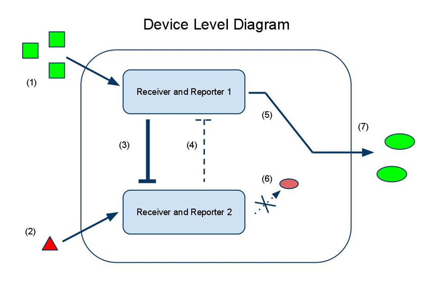
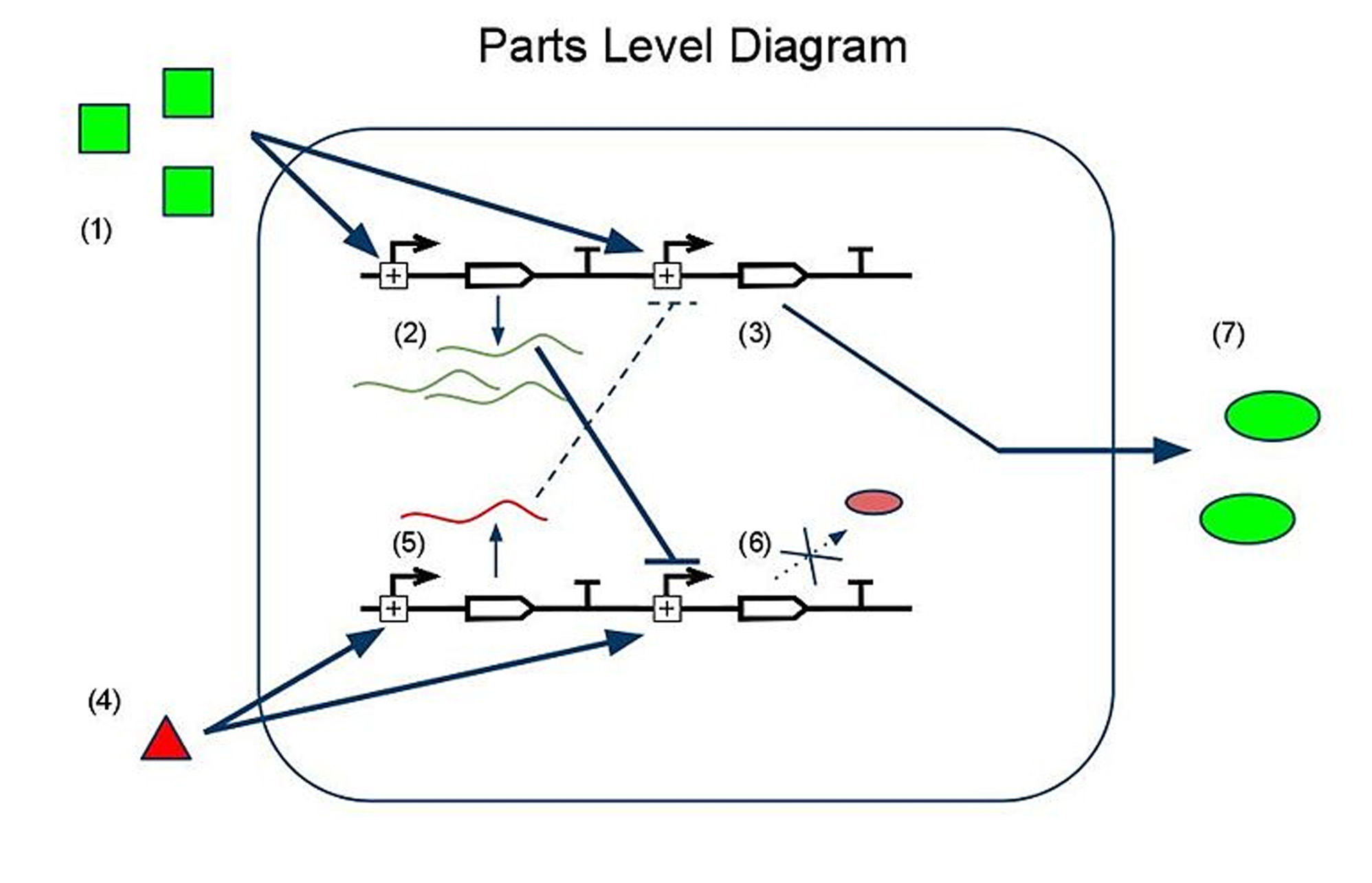
 (1) Input A activates Receiver and Reporter 1. (2) Input B activates Receiver and Reporter 2. (3) There is more input A, so Receiver and Reporter 1 will strongly repress Receiver and Reporter 2. (4) There is less input B, so the repression going the other way is weaker. (5) This leads to the production of output A, and (6) little to no production of output B. (7) The output of the device is either dominated by output A or output B. By seeing which is the case, we can infer whether input A or input B was present in greater amounts.
 "
"
