Team:ETHZ Basel/Modeling/Light Switch
From 2010.igem.org
Modeling of the light switch
Background
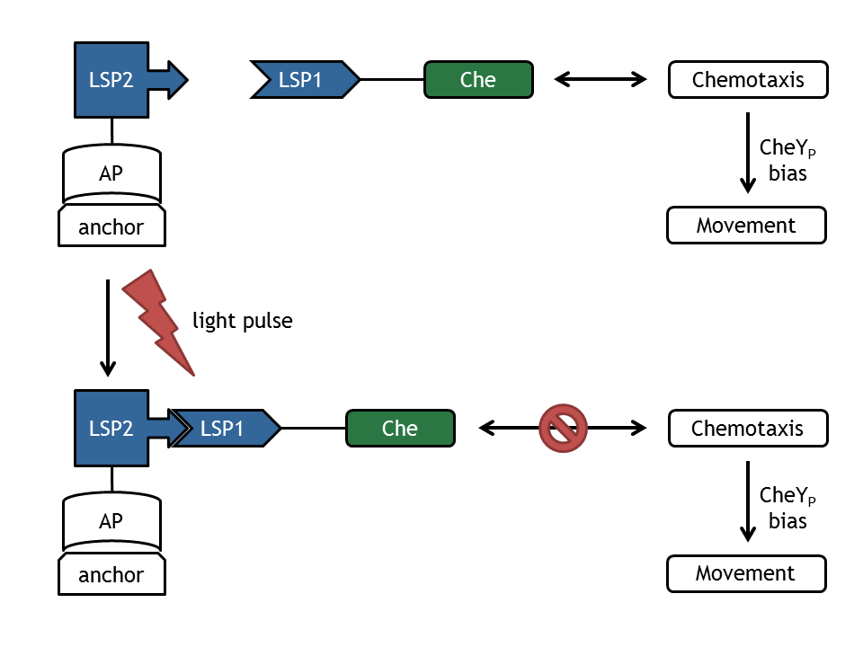
In our biological setup, the relocation of one of the chemotaxis pathway proteins (either CheR, CheB, CheY or CheZ) is achieved by fusing them to a light-sensitive protein LSP1 (either to PhyB or to PIF3), which dimerizes by red light induction with the corresponding LSP2 (PIF3 or PhyB), fused to a spatially dislocated anchor. Since we decided to implement two different models of the chemotaxis pathway (see Sektion [Pathway]), modeling all setups implemented in the wet-lab would have resulted in 16 different models:
|{CheR, CheB, CheY, CheZ} × {PhyB, PIF3} × {Model 1, Model 2}|=16.
Inspired by the modular approach used as the Cloning Strategy in the wet-lab, we decided to decrease the combinatorial explosion by also applying a novel modular approach. Not only did this approach reduce the amount of models by a factor of four, it also allowed to widely separate the differential equations of the chemotaxis pathway from those of the light-induced localization system by simultaneously decreasing redundancies and thus decreasing the danger of slip of the pens. The underlying mathematical model for the light-induced relocation was completely developed by us (for a short discussion of the recently by Sorokina et al. published light-induced relocation system and why we did not use it, see here) as well as - to our knowledge - the approach to couple this model to models of the chemotaxis pathway.
General remarks
In [1] Sorokina et al developed (in vivo) and modeled (in silico) the reversible activation of different phytochromes by red light and their deactivation by far-red light in yeast. Their main model is based on the proteins PhyA and FHL, which have similar properties as PhyB and PIF3 used in E. lemming , as described by the underlying molecular mechanism. In this system, PhyA is fused to the Gal4 bindig domain (GBD) and FHL to the Gal4 transcriptional activator domain. Upon activation with red light, both chimeric proteins bind to each other and the complex can activate the transcription of a lacZ reporter which is under the control of a GAL4-responsive artificial promoter. Upon deactivation with far-red light, the complex dissociates and transcription of the lacZ gene is significantly reduced.
In this model, Sorokina et al assume that PhyA protein sequesteres and only free PhyA can interact with FHL. They state that this interaction is necessary to explain the experimental data presented in the paper, consisting of the strength of fluorescence induced by lacZ over time for different experimental settings. It should be noticed that this signal constantly changes with time in the range of hours.
Implementation
One of the models of system described by Sorokina et al [1] is available in the SBML format [2]. The model was exported to Matlab using SBToolbox2 [3]. However, only the system without input light signals was possible to be reproduced as presented in the paper [1], since the parameters necessary to define these signals were missing.
It was tried to reverse engineer these parameters from the information given in the paper. However, the model available in SBML was slightly different from the model as described in the article: It was not possible to set the strength of the red and far-red light signals directly, but only the derivatives could be adjusted. This modeling decision might have been made to circumvent the problem that some integrators fail to solve a system of differential equations correctly when facing a step change too high in one of the derivatives. To test the model, this work-around was removed and the light inputs were not changed by steps, but by ramps with a length of 1s, which is significant smaller than the other time constants which were relevant for this part of the model. When reproduction of the published data was tried, it was recognized that the strengths of the light signals had to be decreased by approximately 40 fold. Since the exactly inputs of the original simulations were unknown, it was not possible to deduce the reason for this necessary change in the parameters of the model.
Furthermore, several other parameters were not available. These parameters were mainly needed to calculate the fluorescence signal strength from the lacZ concentration. In the paper [1], it was stated that these parameters were obtained for every experiments separatly by fits. To evaluate if the model can reproduce the data in the paper, one of the more important parameters (RLU in [1]) was estimated and the other parameters were set to the standard values from the SBML model, since changes of these parameters had similar effects.
Evaluation of the model
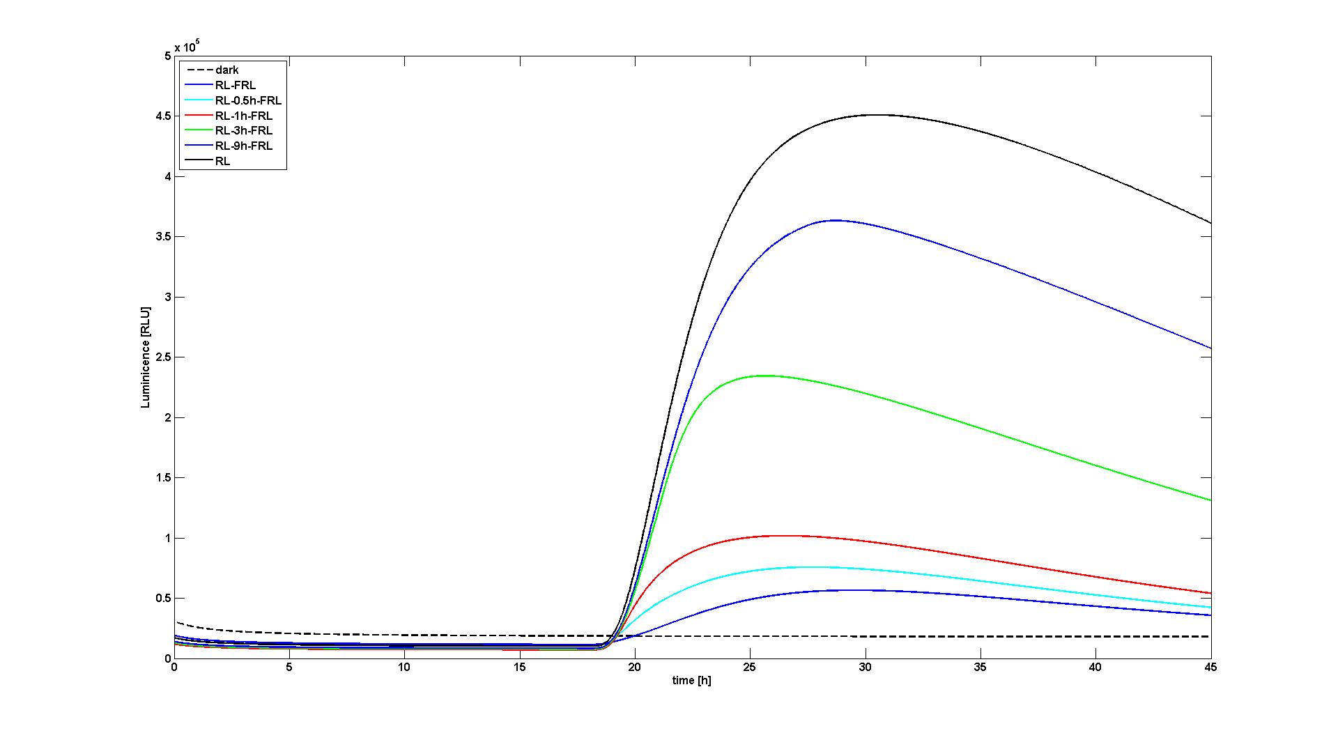
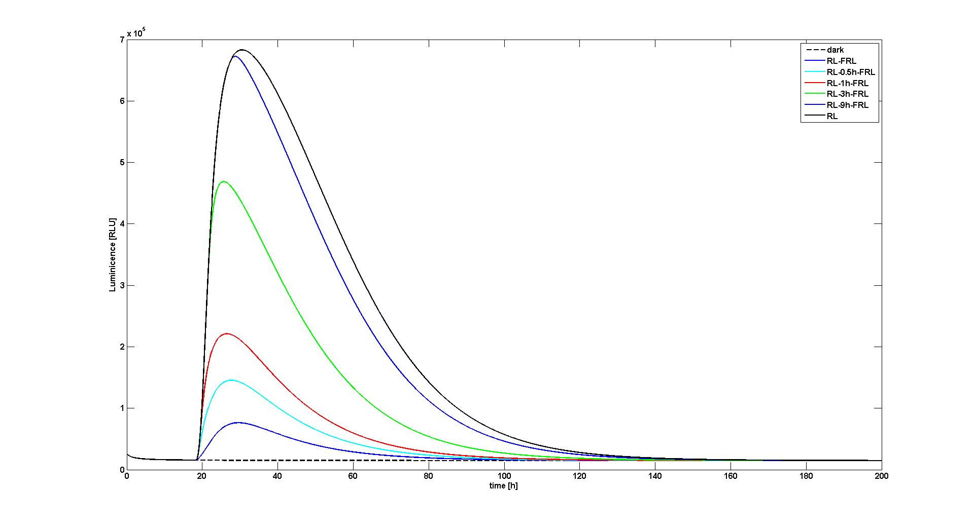
 Figure 1. Reaction of the model to no light input (dashed black curve), red light for 10 min at t=18h (black curve), red light for 10 min at t=18h followed by a 10min far-red pulse after 0h (blue), 0.5h (cyan), 1h (red), 3h (green), 9h (blue). The values for RLU were set so that the data reproduced the measured data as described by Sorokina et al. This figure corresponds to figure 6A in [1]. |  Figure 2. Same as Figure 1, only with the same value for RLU for every experiment (set to a value to reproduce Figure 8A in [1]). |
With the changes made to the model, it was possible to reproduce the data as presented in the paper. Two of the most significant figures (see Figure 1 and 2) were reproduced, which show the response of the system to different light input signals: Whether to no light input at all (dark), a single red light pulse at t=18h lasting for 10 min, or a 10 min red light pulse at t=18h followed by a 10 min far-red light pulse after 0.5h, 1h, 3h, or 9h. All experiments qualitatively and quantitaively reproduced the simulation results obtained by Sorokina et al (see Figure 6B and Figure 8A in [1]).
References
[3] SBToolbox2
 "
"


